I must admit that I am a bit confused by the information that's been presented. My understanding is that the intent behind using Sonarworks SoundID Reference is to achieve a flat response from the loudspeakers at the listening position. Some other desired target curve can also no doubt be created to produce a particular "voicing".
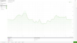
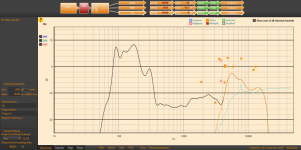
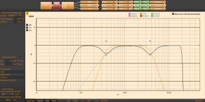
The first frequency response plot (light green) I assume is the raw uncorrected response of the loudspeakers with the Hypex DSP filters in the signal chain.
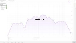
The second frequency response plot (light purple) appears to be the "inverse" frequency correction curve that needs to be applied to the loudspeakers to get them to produce a flat frequency response.
As far as I can tell, what hasn't been plotted for us to view is the frequency response curves of the loudspeakers when the Sonarworks calibration curve is being applied to your speakers. Can you provide us with that information?
The first frequency response plot (light green) I assume is the raw uncorrected response of the loudspeakers with the Hypex DSP filters in the signal chain.
The second frequency response plot (light purple) appears to be the "inverse" frequency correction curve that needs to be applied to the loudspeakers to get them to produce a flat frequency response.
As far as I can tell, what hasn't been plotted for us to view is the frequency response curves of the loudspeakers when the Sonarworks calibration curve is being applied to your speakers. Can you provide us with that information?
So , this is totally embarrassing, one of the reasons why we have been getting an over all problem is, sonaworks id has been running in the backgrond all this time. we switched it off on the desktop but apparently it still runs unless you dont tolaty sign out.. F'''.. My sincere apologies, I am going to start once more and post my new results later, Two weeks wasted due to my f up..

You wouldn’t be the first 😉 There are so many ways to mess it up. One common one that people do is that you have to turn off special sound settings/effects, make the throughput as basic as possible.
I've done similar with an even simpler configuration: a processor in a tape loop. Forgot it was engaged and spent a couple days tweaking and listening to the wrong thing.
It's often quicker the second time through, if that's any consolation.
It's often quicker the second time through, if that's any consolation.
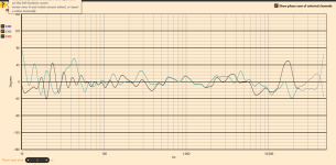
Hello everyone, so after my last little debacle, I managed to pull all the filters together , Here is the Outcome, and yes there still is a over exaggerated BBC Dip but this is only due to the MID gain issue. Phase is ok I think , and the over all sound is excellent,
Attachments
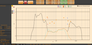
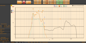
If I read the graph in Screenshot Hz.png correctly, there appears to be a 20dB boost in the bass relative to the midrange. That seems very high. Also, the tweeter output in the range 6kHz to 9kHz is boosted by about 6dB relative to the midrange, which also seems very high. That results in a far from neutral frequency balance. I could understand a total swing of ±3 or ±4dB around a mean line as being quite tolerable, but the results presented indicate a much greater variation.
with this hypex system, this is the only way to balance out the gain over all the frequencies, YES I totally agree that the difference is somewhat puzzling, but this is to be expected “ according to Hypex tech support. The base line staring point was itself from Hypex , bringing the gain down to a satisfactory level was one of the main factors of the overall outcome.
I recognize that the relative gains between the bass, midrange, and tweeter need to be adjusted to achieve a more or less flat response. Do you have a single measurement of the total summed acoustic response of the system, taken at 2 metres listening distance on the axis of the tweeter? I am still a bit confused by what I am seeing in the graphs produced by the Hypex filter design program.
So my original measurements were done with sonaworks this was done before any of the adjustments . As in the photo, also my original plans were just to get as close as possible to the PMC MB2 XBD, all the info is out there but its the modeling of the filters thats the issue. Obviously I am never going to get the Exact pmc outcome but no reason why i cannot get just as good ,, thats why i am here.. again excuse my ignorance on this topic...
Attachments
Last edited:
Also we have tried using REW but will not setup with UAD interface. Installation videos on YouTube are a complete waste of time “ it’s just a bunch of people who like the sound of their own voice. Can’t be bothered with all that. DIY audio is the only place we can trust at the moment. We absolutely get how the Hypex system should work, but ANYTHING we do has a knock on effect when using the filters. If I could pay someone at this point I would do it. It’s becoming a nightmare. It takes me literally 5 minutes to get the basic crossover setup. Not a problem “ the gain is obviously the next step that’s the part that gives the large db change between the hz and lows . Everything else is for the overall sound “ which is pretty good at the moment “ I personally can see no other way that this works. YES it looks all out for shape, but there’s nothing I can do to change that. Thanks 🙏
Last edited:
Lol!!! Yeah that suk😆🤣For $556.40, I would expect a xmax of 36mm instead of 5.2mm.
View attachment 1326003View attachment 1326004
I am still not sure what is actually being shown in the photo that you have provided. I must admit to not understanding what's going on with all the curves that are being displayed in the photo. Note that I am unable to use the Hypex filter design software without a Hypex DSP amplifier to connect it to. That makes providing any help much more difficult.So my original measurements were done with sonarworks this was done before any of the adjustments . As in the photo, also my original plans were just to get as close as possible to the PMC MB2 XBD, all the info is out there but it's the modeling of the filters that's the issue.
The modelling of the low–mid–high filters is relatively easy. The Hypex software seems to manage that quite well. The tricky part is the filter interactions once the natural responses of the drivers come into play, together with their relative geometric offsets.
A key point to note is that higher-order filters can ease the task of blending the acoustic response functions. That's because the overlap region between drivers is less, and the filter response tends to override the response of the driver in the filter's stopband. The Hypex filter design program can add any required delays to get the acoustic filtered responses time aligned so that the filters work more like the theoretical approximation.
In an earlier post, I suggested using 4th-order Linkwitz–Riley filter designs. These would have simplified the blending of the acoustic responses. Some adjustment of relative driver/filter digital delays might still have been needed, but these might have been relatively small for an L–R filter implementation.
As we don't know anything about the filter slopes that were used by PMC in their design, it would be pure chance if we got close to what PMC implemented. The aim is to get a reasonably flat frequency response, which is likely what PMC aimed for. Off-axis directivity is an even trickier thing to attempt to match up with, as many design choices could have been made along the way.Obviously I am never going to get the Exact pmc outcome but no reason why i cannot get just as good ,, thats why i am here.. again excuse my ignorance on this topic...
the softwere
You can download from the Hypex site its free and you dont need to be conected to any amps to use the filter system. I sit in my livingroom, and adjust the filters, then pop over to the studio and upload . its asks you in the setup what amp you have , i use the 503 plate amp.. its works just fine whithout being connected , filter part only ..I am still not sure what is actually being shown in the photo that you have provided. I must admit to not understanding what's going on with all the curves that are being displayed in the photo. Note that I am unable to use the Hypex filter design software without a Hypex DSP amplifier to connect it to. That makes providing any help much more difficult.
I have just had a look at a PMC brochure, where I found this:
The MB2S XBD is a development of the successful MB2S with increased dynamics and LF performance. The addition of the XBD cabinet increases the LF headroom by 3dB below 380Hz that allows a larger room to be driven to greater effect. The 32 element, 4th order passive crossovers are housed in external enclosures which can be mounted to the rear of the XBD cabinets for improved fidelity.
It appears that 4th-order filters are used in the design. I expect that PMC aimed to use the Linkwitz–Riley (L–R) filter topology in the MB2S XBD, which is well-known in pro audio circles. It is relatively easy to implement the L–R filters with the Hypex DSP engine. How to do so is covered in their user manual.
If you implement digital L–R filters for your loudspeakers, using the nominal crossover frequencies of 380Hz and 3.8kHz, then you should be on the road to getting a system response similar to that of the PMC design, in both on-axis response and off-axis response.
Linkwitz–Riley are not in the Hypex filter list , remember I maybe great and bulding things but i am a total beginner when it comes to this ,, so please treat me as such ..It appears that 4th-order filters are used in the design. I expect that PMC aimed to use the Linkwitz–Riley (L–R) filter topology in the MB2S XBD, which is well-known in pro audio circles. It is relatively easy to implement the L–R filters with the Hypex DSP engine. How to do so is covered in their user manual.
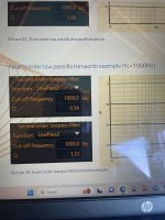
They may not be directly in the dropdown list, by virtue of the Hypex use of biquad digital filter designs. However, L–R filter designs are available by simply using a pair of biquads for each desired 4th-order L–R response function. Here are some relevant snippets from the Hypex filter design manual related to implementing L–R filters:


That’s what I’ve been using, I think one of you guys recommended it before.Try two Butterworth in series of half the order.
Attachments
- Home
- Loudspeakers
- Subwoofers
- Crossover questions