Lucas: I apparently can not do a direct quote. Page 11, your post #102, you give values of new bits & pieces, except for the woofer circuit. What did you end up using for the 72 uf's & where did you get them if they were exact value? I can only find 68 uf's here in North America. Are you still ok with the electros in the bass circuit?
Thanks
DM
Thanks
DM
to DM and Lucas
DM,
if you want to use only electrolytic caps then go to Page 8 of this Thread and to Post #71 for a UK seller of 72uF electros,
BUT, I recommend you go to the Celestion 66 midrange Thread and read my reply to your Post there first.
*******************************************************
Hey Lucas,
thankyou for your identification of the Pass Labs' amplifiers for sound you hear as worthwhile.
I know that Nelson Pass is very experienced, and many of his designs have been liked for sound by many listeners over the years, and he is also an enthusiastic DIYer !
I will look when time is available to see if I can find the schematics for the models you mentioned - eventually I will build an amplifier.
Usually I modify amps, but I have no-where near the knowledge and experience of Nelson Pass in such matters.
Are the ones you built supplied as Kits, or does one buy a schematic from Pass, and parts from where-ever one chooses ?
Ditton 44 Crossover
Hi,
For the benefit of anyone who's interested, I've attached the schematic of the 44 crossover. I reverse-engineered this from a pair with cabinets date-stamped December 1976, all drivers with 'AK' date codes, corresponding with January 1977. I purchased these from the original owner, to the best of my knowledge they've never been apart (until I took them apart) and don't appear to have had any components replaced since manufacture.
A few notes...
Inductor DC resistance meaurements were taken with my 'Solartron 7150 plus' 6-digit bench DMM using the '4-wire' method to ensure accuracy and eliminate errors caused by test-lead resistance.
The inductors were measured by determining the resonant frequency of a parallel-resonant circuit consisting of the unknown inductor and a capacitor which measured 1.536 µF on my Beckman 'DM25L' DMM, then calculating the inductance. As I don't know how accurate this DMM is for capacitance measurements, I cannot guarantee absolute accuracy.
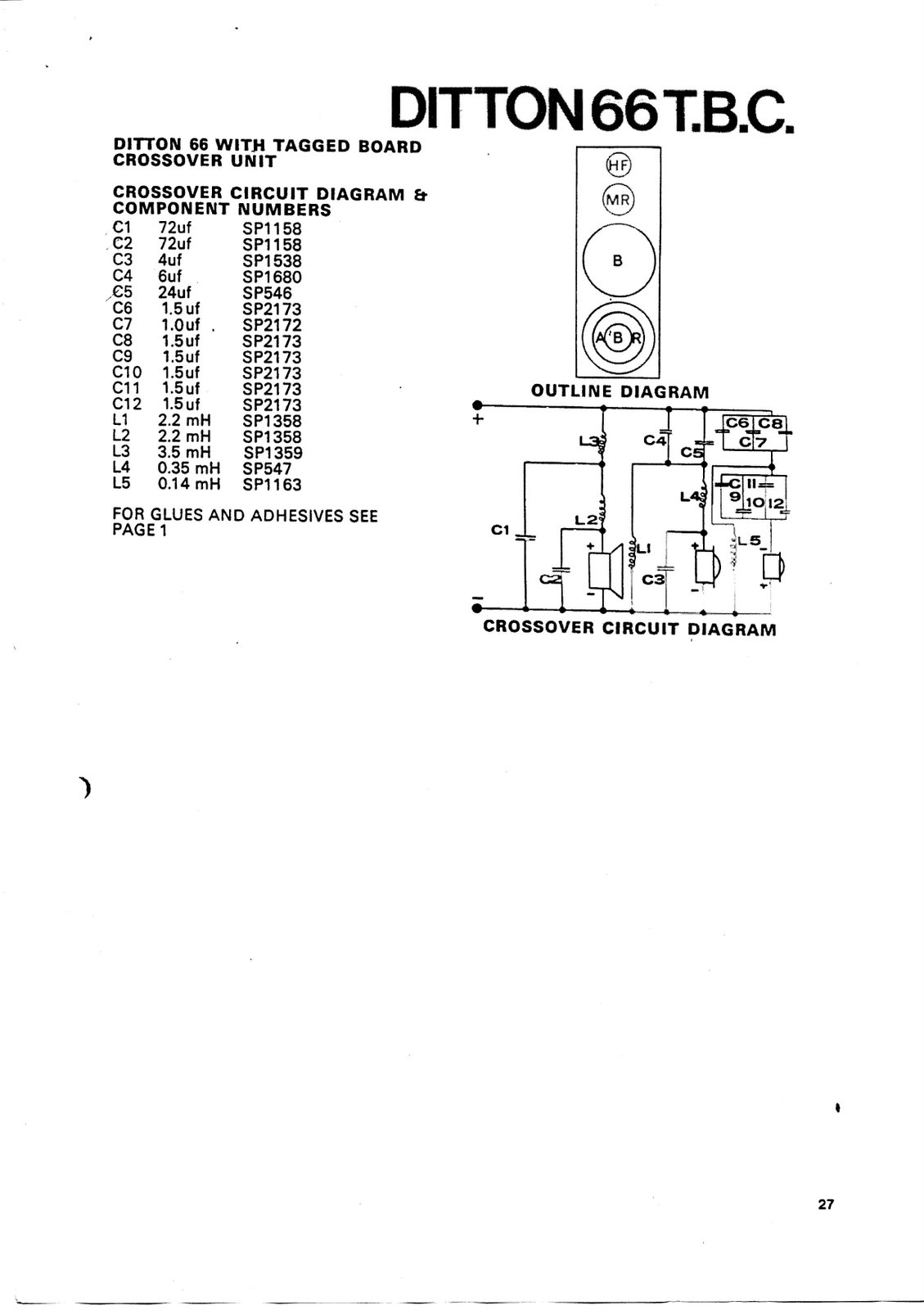
However, one (and only one) of the inductors; L5, Celestion part no. SP1163, is common to the 44 and 66 crossover. The 'Ditton 66 T.B.C.' schematic states that this is 0.14 mH. This broadly agrees with my measurements so it's (arguably) reasonable to assume the rest of the measurements aren't too far off.
The values on the diagram are 'best guess' based on measuring the components in both crossovers. The values weren't consistent, clearly there's some manufacturing tolerance (as well as possible measurement errors) but I'll list the calculated values for the inductors in each crossover, rounded to three digits.
Regards, Kat
Hi,
For the benefit of anyone who's interested, I've attached the schematic of the 44 crossover. I reverse-engineered this from a pair with cabinets date-stamped December 1976, all drivers with 'AK' date codes, corresponding with January 1977. I purchased these from the original owner, to the best of my knowledge they've never been apart (until I took them apart) and don't appear to have had any components replaced since manufacture.
A few notes...
Inductor DC resistance meaurements were taken with my 'Solartron 7150 plus' 6-digit bench DMM using the '4-wire' method to ensure accuracy and eliminate errors caused by test-lead resistance.
The inductors were measured by determining the resonant frequency of a parallel-resonant circuit consisting of the unknown inductor and a capacitor which measured 1.536 µF on my Beckman 'DM25L' DMM, then calculating the inductance. As I don't know how accurate this DMM is for capacitance measurements, I cannot guarantee absolute accuracy.
However, one (and only one) of the inductors; L5, Celestion part no. SP1163, is common to the 44 and 66 crossover. The 'Ditton 66 T.B.C.' schematic states that this is 0.14 mH. This broadly agrees with my measurements so it's (arguably) reasonable to assume the rest of the measurements aren't too far off.
The values on the diagram are 'best guess' based on measuring the components in both crossovers. The values weren't consistent, clearly there's some manufacturing tolerance (as well as possible measurement errors) but I'll list the calculated values for the inductors in each crossover, rounded to three digits.
- L1: 2.10 mH and 2.08 mH
- L2: 2.09 mH and 2.10 mH
- L3, 3.28 mH and 3.16 mH
- L4, 0.653 mH and 0.661 mH
- L5, 0.139 mH and 0.140 mH
Regards, Kat
Attachments
good thinking !
Hi kayelem/Kat -{which name do you prefer for conversations ?},
its good you have posted the measurements here, as hopefully they will be found by Celestion 44 owners.
I note that you are a thinker !
Resonating the inductors with a known capacitance !!
I do this also when applicable, but few people seem to think of doing this.
Regarding accuracy, if you use a capacitor that is close to the largest value your meter can measure the accuracy will be better.
For loudspeaker crossover work if the test capacitor can be of similar magnitude to the caps that will be used in the circuit then the result will be a bit closer to useful even if not fully accurate, and in that case select a test cap that is near to the upper numerals' limit of the relevant Range of the meter.
If the same piece of test equipment is being used for everything, then absolute accuracy is not important because you will have Relative Accuracy
- one Known component, and everything else Relative to it ... presuming here that the Frequency measurements on the drivers are made with the same piece of test equipment ...
If you search around you will find capacitors available in 1% and 2% Tolerance, though not common for the range usually required for crossovers -
greater than 3uF - but its worth obtaining a few so that you will know how close your meter is to accurate.
I bought several, because if only one capacitor it may be a faulty sample ... and I have found one such.
Regarding the inductors:-
the .14mH is the best one there because it is air-cored and thus will not saturate and cause audible distortion when the loudspeaker is driven hard,
and in this case the HF2000 will distort before the inductor !
All the solid cored inductors will saturate, thus likely the sound becomes a bit muddy and/or compresses transients when music is played loudly.
That is one reason that the 66 sounds clearer in both its bass and midrange than the 44.
You can replace the inductors with air-cored, though low resistance ones are quite large , and I think you may already know that ...
How much modifying do you want to do ?
The Celestion 44 owner is working with his SEAS 19TFF1 tweeters now, so we will be deciding the optimum resistors to use with those to match them to the other drivers and the crossover soon.
I will Post results here when decided.
What Vertical Axis do you prefer to listen on with your 44s :-
On-axis to the tweeters ?
On-axis to the mids' cones ?
Slightly below mids' cones axis a little down towards woofers ?
In the era when those speakers were designed the usual practice was to optimise the crossover for flattest possible frequency response on-axis to the mids' driver -{the Squawker, as that driver was called then !}- and that is what I will be designing for unless requested otherwise.
Finally, what do you think of the sound quality of that mid-range cone driver ...
in comparison to whatever quality midrange you have heard from other loudspeakers ... ?
Last edited:
Personally Alan, I think that the midrange cone is much nicer than the mid dome of the 66s and 551s. Now it may be that these mid domes get old and tired easily, and the ones I've heard were a bit honky, but in my experience of those in the 551, they were not good. With such a limited frequency range, they are also much harder to design for without dips at the crossover points. I like these cones. If you isolate any midrange driver, they sound like the crappest old kitchen radio set ever, or even unpowered Walkman speakers, if you remember those - so funny really that we get so het up about qualities in something that's pumping out a tiny amount of kitchen radio noise. I know it's important, of course, but it always amazes me how much of what we think of as midrange is dealt with by the woofer.
Anyway, having said all that, I think I prefer midrange axis.
I have removed the tweeter 1.5Ω completely from the new Seas tweeter and reversed the polarity (to factory spec reverse polarity) to have a good old re-listen before I move forward. If I find it a bit treble rich, I will of course do as you say and attenuate at the tweeter circuit input. I'm having a tough time listening properly, however, as my power-amp has gone into oscillation recently and I have no idea why...yet! Perhaps I've buggered it with all of this speaker messing - eek!
Anyway, onwards and upwards...
amplifier problem and loudspeaker load, + midrange drivers
Lucas,
if you have engaged in an act of buggery with your amplifier then do not be surprised that it has gone into oscillation - it is likely screaming in protest !
More seriously,
and relevant to your description elsewhere about this Pass Labs amplifier.
A wide-bandwidth, extended high frequency amplifier is very sensitive to:-
- layout/placement of internal components
- the solder joints
- the type of Load its feedback loop sees after connection to the loudspeaker.
I can comment only on possible problems with the Load:-
perhaps the amp is designed to operate into a fixed range of load impedances, though minimum 4 ohm and maximum 16 ohm at least,
would be reasonable to expect for a Pass Labs power amp, UNLESS it is a Current Drive amp which has to be used with a high impedance load ..?
Nelson Pass does publish circuits for this latter type, so check what the amp is specified for.
If it is a conventional, low impedance load amplifier, its specification may include a Maximum Phase Angle for the Load it can drive.
Your 6.1 ohm DC resistance tweeter has an approximately 7.2 ohm impedance in the middle of its operating bandwidth, and that is sufficiently high to cause a high phase angle/steep slope in the total impedance load around the 5 kHz region when it is connected to the Celestion 44 treble crossover filter ...
and more-so when you had the 1.5 ohm resistor connected to the output of that filter ...
perhaps this has caused some internal damage to the amplifier.
Ask Pass Labs' Customer Service to inform you the "Maximum Phase Angle at Minimum Impedance" Load specifications for this amplifier.
For phase angle load safety for when you get the amp working,
connect a 15 ohm/10 watt wirewound resistor in electrical Parallel with the tweeter.
That is, connect the resistor across the Output connections of the treble filter from the +ive to the -ive wire connection points.
This is for load when the SEAS tweeter is also connected.
If you are also testing the crossover circuit with no tweeter connected then use a resistor of not less than 3.9 ohm nor greater than 5.6 ohm there ... also in 10 watt.
5.6 ohm will be the most useful because that is the closest to what the final treble load will be after modification to impedance-match the SEAS tweeter, but if you can't find a 5.6 ohm, then 4.7 ohm will suffice for simple testing.
Do not test any amplifier into that crossover if any of the drive units are disconnected !
Connect 4.7 ohms/10 watt as substitute for the woofer,
and whatever ohms is equal or slightly greater than the DC resistance of the mid-cone as substitute there.
{What is the DC resistance of those mid-cones ?}
These do not need to be expensive resistors.
Buy cheap 10 watt wirewounds from a local shop to use whilst you are experimenting,
but if you have to buy via Mailorder then buy the 15 ohm in at least Welwyn W23 or W24 series
-{whichever is suitable length to fit - W23 has 38mm/1.5 inch long body and W24 has 52mm/2 inch},
and buy a pair of 1 ohm in Welwyn WP4S preferably, or WA84 next, or W21 at least,
because this 15 ohm with 1 ohm combination is the most likely pairing you will be using later.
If you buy cheap 15 ohm elsewhere, you can use with your existing 0.5 ohm and 1.5 ohm Welwyns safely to decide which causes closest to the attenuation you prefer for the tweeter.
It is possible the Parallel resistor may have to be 12 ohms if you want a lot of attenuation,
but my closest estimate is 15 ohms based on what you have described to date.
***********************************************************
About the midrange drivers:-
It is easier to manufacture a reasonable audio quality cone mid at moderate cost than dome mid.
The Celestion MF500 and MD500 domes were exceptional products for their era, and it is possible the later MD750, or whatever it is in the 551 and 662, is not as good a driver - I suspect reduced manufacturing cost to enable the 551 and 662 prices to be set lower than if with an equivalent to MD500 quality dome was used ... but I do not know for sure.
If your listening experience of the MD750 { correct model number ?} is based on what your neighbour Lorien has, then the audible result may not be a fair assessment because he had a mixture of different Impedance drivers and Crossovers and may not then have had each correctly load-matched during his experiments.
He has not posted any more in his Thread about that project for several months, thus I do not know what he has done since.
Last edited:
Hi Alan
My amp is fine. It's actually an Audiosector Gainclone using LM3875 chips. The problem was EMI caused by a landline phone nearby, which, combined with the unshielded wooden case, made it pretty receptive to this unusual throbbing EMI those things give off. Moving it a single metre away was enough.
I have yet to start the Passlabs F5. I'm collecting all the parts right now.
You could be right about Lorien's speakers. He does do some rather unorthodox experiments with his crossover circuits and drivers. I'm sure the dome mids are good as they have such a good press.
I am moving house (me, wife, 2 kids) 200 miles to Bristol this week, so I'm not going to be able to do any hi-fi related shenanigans, on pain of death by wife, but at the earliest opportunity I shall be placing some .5Ohm wirewounds at the input to my tweeters, and I shall report back...
A Manana
Lucas
Hi,
I'm back! (The SEAS tweeters took rather a long time to arrive, so I've been fixing dead test gear in the meantime.)
Ditton 44s cope with everything I throw at them, so I'm just aiming to 'bring them up to scratch' (replacing any degraded components) and maybe improve them a bit with better tweeters.
Progress so far: I've ordered four 72µF NP electrolytics after finding one of them measured 7.3µF (with ESR of 12Ω.) The others (in one crossover, at least) test good so they can stay for now, but I'll replace them later anyway.
My reference mic appears to work (I haven't used it in years.) I've unearthed a preamp which has the requisite phantom power capability, then modified it by adding a balanced line-driver. The computer system I'll be using for measurements lives upstairs, so I'm making sure the system works with the power amp and mic pre-amp on the opposite end of 20m of balanced cable to the audio interface (Edirol FA-101.) Response/distortion measurements so far suggest it could be 100m of cable without making any difference.
I'll be leaving one speaker unchanged as a reference, while working on integrating the SEAS tweeter with the other one. Once my ears and my test gear tell me I've got the crossover mods right, I'll do the same mods to the other one.
(Then I can get back to restoring a turntable and designing/building a cartridge pre-amp; what I was up to before frying a tweeter. Still, it meant I discovered both tweeters were probably in the process of failing and some crossover components need replacing anyway, so I can't complain!)
In the first instance, I think I'll just connect the new tweeter up with the crossover components unchanged (bar replacing faulty components), get some response plots, listen to it, then take it from there.
Regards, Kat
I'm back! (The SEAS tweeters took rather a long time to arrive, so I've been fixing dead test gear in the meantime.)
My initials are 'KLM' (hence the forum username), 'Kat' is short for 'Katharine' and I'm possibly known to as many people as 'kayelem' as 'Kat'... so either works.Hi kayelem/Kat -{which name do you prefer for conversations ?}
I've since acquired a Marconi TF2700 bridge and re-measured the inductors from one crossover. I'll post the new measurements when I've measured the ones in the other crossover. My original measurements are close anyway.its good you have posted the measurements here, as hopefully they will be found by Celestion 44 owners.
I may do that; if I do I'll probably wind my own. (This is partly why I got the bridge. Wind on a few more turns than calculated, measure it, unwind until it's right.)You can replace the inductors with air-cored, though low resistance ones are quite large , and I think you may already know that ...
How much modifying do you want to do ?
I have them on stands; normal listening position is on-axis with the mids.What Vertical Axis do you prefer to listen on with your 44s :-
On-axis to the tweeters ?
On-axis to the mids' cones ?
Slightly below mids' cones axis a little down towards woofers ?
Up there with the best of them; why I have no desire to replace these speakers with anything else. I listen to a lot of different genres of music so I need a system which will cope with everything from very early jazz/blues to current electronic dance music (and much of what lies in between.)Finally, what do you think of the sound quality of that mid-range cone driver ...
in comparison to whatever quality midrange you have heard from other loudspeakers ... ?
Ditton 44s cope with everything I throw at them, so I'm just aiming to 'bring them up to scratch' (replacing any degraded components) and maybe improve them a bit with better tweeters.
Progress so far: I've ordered four 72µF NP electrolytics after finding one of them measured 7.3µF (with ESR of 12Ω.) The others (in one crossover, at least) test good so they can stay for now, but I'll replace them later anyway.
My reference mic appears to work (I haven't used it in years.) I've unearthed a preamp which has the requisite phantom power capability, then modified it by adding a balanced line-driver. The computer system I'll be using for measurements lives upstairs, so I'm making sure the system works with the power amp and mic pre-amp on the opposite end of 20m of balanced cable to the audio interface (Edirol FA-101.) Response/distortion measurements so far suggest it could be 100m of cable without making any difference.
I'll be leaving one speaker unchanged as a reference, while working on integrating the SEAS tweeter with the other one. Once my ears and my test gear tell me I've got the crossover mods right, I'll do the same mods to the other one.
(Then I can get back to restoring a turntable and designing/building a cartridge pre-amp; what I was up to before frying a tweeter. Still, it meant I discovered both tweeters were probably in the process of failing and some crossover components need replacing anyway, so I can't complain!)
In the first instance, I think I'll just connect the new tweeter up with the crossover components unchanged (bar replacing faulty components), get some response plots, listen to it, then take it from there.
Regards, Kat
Capacitors for bass filter, etc ...
Hi Kat,
its good you are back !
I'll have to be brief today as I have little time available.
Given your intention to wind good inductors for the relevant sections of the x-overs,
I think using NP electro caps in the bass section will reduce the potential of possible improvements.
I would cancel the order for those.
There are 70uF polypropylene caps available in UK, though physically large size as are 400 volt rated.
I'll Post the address for those as soon as I find it !
Alternately, there are 36uF/250 volt polypropylene caps available via Mailorder from France and Canada if you can buy in such way.
These are moderate size, and can be piggy-backed so as to fit on the boards without too much problem for parallel pairs to sum to 72uF.
I'll find and Post the addresses if you prefer such .. ?
For the SEAS tweeter, if retaining the .14mH inductor, it seems about 3.6uF will be closest to the optimum for the Input cap
-{or 2 x 1.8uF, or 3 x 1.2uF depending on the Brand you can buy}-
and a little over 10uF for the output cap.
I'll be finalizing that soon, and also the load matching resistors to integrate those tweeters into the 44 crossover.
I have to go now, but Post more commentary if you wish.
Last edited:
The 662 had a single massive inductor in the bass (I haven't measured it) and a single cap. I have a schematic with the cap sizes and the layout, but not the inductor values. It also had a lot of caps generally and a resistor as standard. You can see the inductor in this photo. You may want to go with the option of a single huge inductor and a single cap. It may sound better:

why does post150 pic not download?
when selecting that 3u6F for the tweeter. Buy the 3u3F that you can afford.
Measure it and then add on a (cheap) low value parallel capacitor to bring up the total capacitance to what you think you need. Listen and adjust the low value capacitor, since it's very likely that component tolerances will require something other than exactly 3u6F for your crossover.
When you find a good value for the parallel cap, go and buy that value that you can afford.
I don't know Andrew. Posting and viewing pictures on this site is very last century, as admitted by the mods.
If you want to see it, right click/control click, and select "open in new tab/window"
So Andrew, do you have Celestions too?
If you want to see it, right click/control click, and select "open in new tab/window"
So Andrew, do you have Celestions too?
only a pair of 18inch fellows. Oh, and some rather old HF1300mk2 that do not interfere with CRT picture.do you have Celestions too?
Ah, that worked. I can see!
Control+click did not work, but both right click, other tab and other window, worked perfectly.
All the inductors are oriented in the same direction. They will interfere with each other, particularly where they are close together.
Rotate them so that you use the three different axial orientations, X, Y, Z.
The two that are more remote. Make them different from each other and different from the next closest one.
Last edited:
Transient Response
Sorry Andrew,
but this method does not render accurate sound reproduction.
For capacitors used simply to store electrical charge - basically a DC voltage application - or to filter AC noise - capacitors can be combined as you describe, but Music Signal is AC, and has complex Transient behavior.
The small size parallel connected capacitor passes the leading edges of transients much faster than the larger main capacitor and thereby changes the waveform of the signal.
The effect is audible ... and as several experimenters have written about this over the years, obviously they hear this effect ... not only myself.
Some listeners like this effect and some don't.
It is a Sound Effect - the signal is changed.
To combine capacitors in Parallel with no Transients' changes to the signal, the relevant capacitors must all have the same Pulse Rise Time.
That is easily achieved with Axial format caps, by using caps of the same body length.
Best is to use caps of equal values, eg: as I advised 2 x 1.8 or 3 x 1.2 for 3.6uF.
Caps of different values have different charge/discharge times, even those which have the same Pulse Rise Times, and this is also audible, albeit less so, however some listeners other than myself have reported such, including in this Forum in several threads.
See earlier in this thread, there is an example.
when selecting that 3u6F for the tweeter. Buy the 3u3F that you can afford.
Measure it and then add on a (cheap) low value parallel capacitor to bring up the total capacitance to what you think you need. Listen and adjust the low value capacitor, since it's very likely that component tolerances will require something other than exactly 3u6F for your crossover.
When you find a good value for the parallel cap, go and buy that value that you can afford.
Sorry Andrew,
but this method does not render accurate sound reproduction.
For capacitors used simply to store electrical charge - basically a DC voltage application - or to filter AC noise - capacitors can be combined as you describe, but Music Signal is AC, and has complex Transient behavior.
The small size parallel connected capacitor passes the leading edges of transients much faster than the larger main capacitor and thereby changes the waveform of the signal.
The effect is audible ... and as several experimenters have written about this over the years, obviously they hear this effect ... not only myself.
Some listeners like this effect and some don't.
It is a Sound Effect - the signal is changed.
To combine capacitors in Parallel with no Transients' changes to the signal, the relevant capacitors must all have the same Pulse Rise Time.
That is easily achieved with Axial format caps, by using caps of the same body length.
Best is to use caps of equal values, eg: as I advised 2 x 1.8 or 3 x 1.2 for 3.6uF.
Caps of different values have different charge/discharge times, even those which have the same Pulse Rise Times, and this is also audible, albeit less so, however some listeners other than myself have reported such, including in this Forum in several threads.
See earlier in this thread, there is an example.
Last edited:
risk to change the filters
Hi Lucas,
if one applies a single inductor/capacitor section to the woofer of the 44 the sound will be changed, and I think more likely for the worse.
The filter section for the 662 -{and similar for the 442}- are for a different woofer, and for a higher cross-over frequency,
and quite a number of 44 and 66 enthusiasts did not like the 442 and 662 when they were introduced.
Each type has its own distinct sound, and it seems from reports around the net in recent years that the 44/66 types are preferred to the 442/662 types.
Yes, there are other differences between these vintages of models that cause other differences between their sounds,
but for the 44/66 woofer I think Celestion got it very close to optimum with their 4-section filter.
The 2-section filter in the 442/662 may be there simply because it was cheaper, not because it was better.
The 662 had a single massive inductor in the bass (I haven't measured it) and a single cap. I have a schematic with the cap sizes and the layout, but not the inductor values. It also had a lot of caps generally and a resistor as standard. You can see the inductor in this photo. You may want to go with the option of a single huge inductor and a single cap. It may sound better:
Hi Lucas,
if one applies a single inductor/capacitor section to the woofer of the 44 the sound will be changed, and I think more likely for the worse.
The filter section for the 662 -{and similar for the 442}- are for a different woofer, and for a higher cross-over frequency,
and quite a number of 44 and 66 enthusiasts did not like the 442 and 662 when they were introduced.
Each type has its own distinct sound, and it seems from reports around the net in recent years that the 44/66 types are preferred to the 442/662 types.
Yes, there are other differences between these vintages of models that cause other differences between their sounds,
but for the 44/66 woofer I think Celestion got it very close to optimum with their 4-section filter.
The 2-section filter in the 442/662 may be there simply because it was cheaper, not because it was better.
Last edited:
That's also what I understood to be the case, Alan.
Also, I have heard previously that the orientation of air-core transformers should always avoid the core itself being in line with other components, like pointing at them. Putting them all in this flat orientation on the PCB does just that. I don't know what to believe now. Why do you say they should be put on all axes Andrew?
Also, I have heard previously that the orientation of air-core transformers should always avoid the core itself being in line with other components, like pointing at them. Putting them all in this flat orientation on the PCB does just that. I don't know what to believe now. Why do you say they should be put on all axes Andrew?
Hi Lucas,
if one applies a single inductor/capacitor section to the woofer of the 44 the sound will be changed, and I think more likely for the worse.
The filter section for the 662 -{and similar for the 442}- are for a different woofer, and for a higher cross-over frequency,
and quite a number of 44 and 66 enthusiasts did not like the 442 and 662 when they were introduced.
Each type has its own distinct sound, and it seems from reports around the net in recent years that the 44/66 types are preferred to the 442/662 types.
Yes, there are other differences between these vintages of models that cause other differences between their sounds,
but for the 44/66 woofer I think Celestion got it very close to optimum with their 4 section filter.
The 2 section filter in the 442/662 may be there simply because it was cheaper, not because it was better.
I can hardly believe that it was cheaper with that massive inductor, but yes, the 662 may well have been a less favourable speaker overall. Whether that can be attributed to the bass circuit is another matter, but I agree that the 2x cap, 2x inductor circuit of the 44/66 does work well, despite being a very unpopular technique with certain posters in this thread (Tinitus).
I have not heard criticisms of active crossovers like the one you made, but only positive comments. Raving even! It's a big process though, and there are very few people using such a system in small hi-fi systems. Those that do are usually converted, in my experience, but I have never knowingly heard a small signal crossovered system, active or passive, other than PA systems, so I don't know what I can expect. It does make a lot of sense to me though.
Orientation of closely spaced Inductors, and about Costs, etc ...
Andrew is correct in his comments about the inductors.
There is a Link , posted somewhere in the Celestion 66 midrange Thread,
to a web-site which shows pictures of inductor placements, and measurements of the interference effects - some are quite substantial.
Unfortunately there was, and still is for some, Accounts' personnel employed by many of the Loudspeaker manufacturers who demanded that all possible costs be cut, regardless of some detriment to the sound, so long as the casual or uneducated listener did not hear any major problem,
thus smaller than optimum size circuit boards were used, etc ...
and this includes why the cheaper, more easily saturated inductors were used in the Celestion 44 than in the premium 66 model.
KEF still use fairly mediocre quality capacitors and tiny cramped circuit boards in most of their loudspeakers, including in at least some of their expensive models, and B&W only use good quality caps in their most expensive models, to mention only two offenders ...
One large inductor does cost less than two somewhat smaller, because there is the labour costs involved in winding them and installing them,
not only the cost of the copper.
One has to design and apply very carefully to get a 4-section filter to work without audible detriment.
It is not Simple for a 2-section filter, but it is usually simpler than for a 4-section filter ... if one likes the characteristic sound/s of 2-section filters ... there are two applications of 2-section filters ... one I like the sound via, and the other I usually don't, except as a sound effect in specific circumstances.
I have to go now ... more about Active an DC offsets at some time in the future ... if you decide to proceed there.
Last edited:
Hi,
My analysis of the 44 crossover is that we have a 4th-order low-pass filter for the bass driver, 2nd-order band-pass filter for the mid and 3rd-order high-pass for the treble.
Replacing a 4th-order filter (24dB/octave) with a 2nd-order filter (12dB/octave) for the bass driver would be unlikely to work. Celestion will have chosen to use a steep filter for the bass driver for a reason.
I suspect the 2nd-order band-pass filter for the mid driver is combining with the roll-off of the driver itself to produce slopes which match those of the bass/treble drivers and their filters.
The phase shift at the crossover frequency of the tweeter's filter is the reason why the tweeter's phase is reversed with respect to the mid - if it wasn't, the mid and tweeter would be out of phase with each other at/around the crossover frequency, producing a notch in the overall response. This is why it "sounds better" when the tweeter appears to be wired "backwards". (Incidentally, the depth of the notch when the tweeter's phase is reversed can be a good indication of how well integrated the mid and tweeter are. I'll be checking that.)
Regarding capacitor replacement, my aim at present is to determine how well the speakers perform when returned to approximately original condition. Hence I'm replacing defective NP electrolytics with new NP electrolytics and leaving the ones which aren't faulty in place, having tested them for capacitance, electrical leakage resistance and equivalent series resistance.
Replacing ferrite-cored inductors with air-cored ones is still only a 'maybe'.
Replacing ferrite-cored inductors with air-cored inductors and replacing NP electrolytic capacitors with (usually expensive) still leaves me with a passive crossover (and a fairly complicated one at that.) There are a lot of components between amplifier and drive units.
Rather than playing around with different types of components, on balance, I think I'd rather put my time and money into removing them altogether. That means designing/building a pair of three-channel amplifiers with an active crossover in each (with the crossover frequencies and filter slopes of the original passive one.) Each driver is then connected directly from its own amplifier, with nothing between amp and driver but wire (not much wire as each amp can be positioned near its respective speaker.)
Designing filters is a lot easier when they're loaded by a high impedance which doesn't vary and they aren't required to handle significant power.
I have heard active systems. Mostly the main monitoring systems in recording studio control rooms (the big ones built into the walls, not the little ones balanced on the meterbridge of the console...)
Regards, Kat
- Status
- Not open for further replies.
- Home
- Loudspeakers
- Multi-Way
- Crossover nightmare!!!!!!!