scientific wire company (SWC) sell in 100g 500g and 1kg on plastic reels.
~£12/kilo
scientificwire.com
~£12/kilo
scientificwire.com
I guess that's possibly a slight advantage in that it's already on plastic reels, which may be an appropriate size for the inductors. Is that likely? Otherwise, it's much the same price, no?
OT: Andrew - I've got to talk to you about the remote control units - that pot wiring makes no sense whatsoever! I've removed it from the PCB, and still it makes no sense.
OT: Andrew - I've got to talk to you about the remote control units - that pot wiring makes no sense whatsoever! I've removed it from the PCB, and still it makes no sense.
Pretty much the same price.
A 1kg reel (~82m) would do two 2.1mH inductors (38.7m), so you'd need two reels. Another two 1kg reels would be needed, one each for the two 3.2mH inductors (50.1m), so you still need 4kg total, at £48 plus whatever P+P.
If anyone's intending to do this, I'd suggest increasing the wire size (to reduce DC resistance) while leaving it possible to get all six out of one 4kg reel.
Check the circuit. You go to the trouble of using nice thick cable between amp and speakers, but then the two inductors in the bass section add 1.3Ω DC resistance between amp and driver...
You want better inductors? That means eliminating the ferrite core, which means more turns of wire for a given inductance, hence thicker wire is needed just to get the same DC resistance as the ferrite-cored ones. Thicker wire still is then needed to reduce DC resistance.
IMO it's best to make the formers to the required size. Otherwise you have to calculate height/radius/turns, look for a former that's close, then work out what inductance you'd get using that former and adjust the number of turns. (Which would increase if the original calculation produced the optimum height/radius, increasing DC resistance again...)
Kat
Apologies for today, but a little to continue progress
Hi Kat and Lucas,
it is good Kat that you are experimenting as that allows one to learn things
- says I from much experience of such !
however you have posted so many points that I do not have time to address all the relevent ones today, and in fact little time remaining at all after re-reading earlier posts to ensure I have the whole picture in mind ... (and then posting to clear another in the 66 midrange thread).
I will get back to this next week, but for now, if you have time interim, Post the DC resistances for all the inductors in the 44 crossover ...
with no short-circuit paths connected through capacitors charging up, etc ... , but I think you will know about that !
I will comment on the 44's potential with new inductors after I know the DC resistances of the existing ones.
4.8 ohm is relevant only to the HF2000 regarding Impedance for load termination, not to the SEAS H737, for which other load Impedances can be used.
I calculated for the SEAS using an Impedance that will allow use of the existing .14mH inductor, thus base your calculations on 5.7 <--> 5.9 ohms if you want to keep that inductor.
I will explain this more fully next time.
I have some ideas about use for your 1uF Russian caps.
Are they Military Spec ?
Do you know their Dielectric type ?
Some enthusiasts have obtained Russian Military Polystyrene dielectric caps - if you have those - great !
Sansui AU-317II !! - is it in good condition, or have you restored it ?
Likely all the electrolytic caps in it will need replacing ...
***************
Yes Lucas,
15 ohms parallel, then 1 ohm Series, if you want about -1.6dB attenuation, and likely close to flat response.
I'll Post about the apparent 3dB that Kat estimated next week, if such is still relevant ... or did you realize an error there Kat ?
Listen with the resistors in, plus the 10uF cap whilst the 3.9uF cap is still there, and report your impressions.
3.9 instead of 3.6uF will not cause any damage to the tweeter, at least not whilst you have the resistors in and 10uF on the output.
Last edited:
Hi Alan,
Still haven't bought that stuff, as I have a 40 item list I'm collating, costing nearly £100, but when it arrives, I will do the tweeter mods ASAP.
I'm also considering something quite severe.....removing the back of the speakers and making them completely open baffle. Removing the inner mids box too. It may need some reinforcements, and a rethink of the soft materials inside. Seriously now, I think it may well sound mind-blowing. If it doesn't, I'll put a replacement birch ply back on there. I also wish the 44s were on 2 foot stands, more like the 66s on 1 foot stands.
Efficient Air Core Coil Winding: Brooks Coil
I've only glanced over the last 20 posts or so of this thread, but someting about winding inductors caught my eye:
Some guy a long while back already figured out the "best case" situation of what geometry makes the most inductance with a constant length of wire (thus the lowest resistance for a particular inductance and a particular diameter wire), it's called a Brooks Coil. It's described at the bottom of this page (as well as elsewhere online):
Multi layer air coil design and calculator
The equation doesn't tell you what wire size fits in that area - that's left as an exercise for the student. 🙂
With the popularity of multi-way speakers and crossovers both commercial and DIY, I wouldn't be surprised to find out this was worked out decades ago.
I've only glanced over the last 20 posts or so of this thread, but someting about winding inductors caught my eye:
If you've seen the formulas (as in another link for calculating air-core inductors in this thread), you see that inductance varies with coil geometry. Also, a larger diameter coil (ignoring for the moment how the inductance changes with diameter) takes more wire for the same amount of turns, and so will have more DC resistance.I guess that's possibly a slight advantage in that it's already on plastic reels, which may be an appropriate size for the inductors. Is that likely? Otherwise, it's much the same price, no?
Some guy a long while back already figured out the "best case" situation of what geometry makes the most inductance with a constant length of wire (thus the lowest resistance for a particular inductance and a particular diameter wire), it's called a Brooks Coil. It's described at the bottom of this page (as well as elsewhere online):
Multi layer air coil design and calculator
The equation doesn't tell you what wire size fits in that area - that's left as an exercise for the student. 🙂
Yes, it can take good math skills to optimize all these things. You could sort out these formulas to solve for what you want, then do some calculus so you can plug in inductance and resistance you want, and the formulas give length and diameter of wire, and dimensions of the appropriate Brooks coil - I could perhaps do this, though with how long it's been since I've done much calculus, I'd be faster getting getting good-enough approximations on a spreadsheet....You want better inductors? That means eliminating the ferrite core, which means more turns of wire for a given inductance, hence thicker wire is needed just to get the same DC resistance as the ferrite-cored ones. Thicker wire still is then needed to reduce DC resistance.
IMO it's best to make the formers to the required size. Otherwise you have to calculate height/radius/turns, look for a former that's close, then work out what inductance you'd get using that former and adjust the number of turns. (Which would increase if the original calculation produced the optimum height/radius, increasing DC resistance again...)
Kat
With the popularity of multi-way speakers and crossovers both commercial and DIY, I wouldn't be surprised to find out this was worked out decades ago.
no.If you've seen the formulas (as in another link for calculating air-core inductors in this thread), you see that inductance varies with coil geometry. Also, a larger diameter coil (ignoring for the moment how the inductance changes with diameter) takes more wire for the same amount of turns, and so will have more DC resistance.
Using a fixed diameter of wire, one gets minimum resistance for the required inductance by winding a coil that has nearly a square cross section and the finished diameter is approximately 4times the width of the coil.
This requires a core/bobbin diameter of approximately 2times the width of the bobbin.
Think back to the coils in your radio receiver. They were short fat coils to maximise the Q of the inductor. High Q requires low resistance.
The "Brooks" coil shown in the link is nearly the best geometry for minimum resistance, but not quite.
Last edited:
Hi Everyone
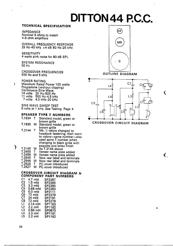
Sorry to crash into this thread but I was communicating with alan-1-b about Celestion 66s and he said it might be helpful if I were to post the circuit diagrams for the Ditton 44 crossovers here. Apologies if someone has already done this - I haven't read this thread yet although I am working on it! Just by way of background I'm a complete beginner at DIY. I own a pair of late model Celestion 66s which I currently have hooked up and also a pair of late model 44s which I'm about to put back into use for the sake of making some comparisons with the 66s.
Anyway here goes. Please note there are two crossover diagrams, one for the usual wired type and one for the rarely seen PCB. I will read this thread with great interest.
An externally hosted image should be here but it was not working when we last tested it.
An externally hosted image should be here but it was not working when we last tested it.
An externally hosted image should be here but it was not working when we last tested it.
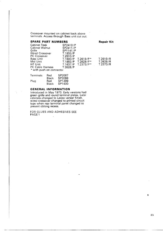
Crossover differences ...
Hi rwtomkins,
no need to apologize - you are very welcome here -{at least by me} !
Thankyou for posting the Schematics/Parts Lists' pages.
These are very interesting, though as we found with the Celestion 66
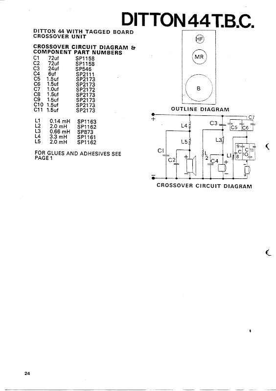
there are variations amongst 44 samples which are different to both the published Ditton 44 T.B.C. and P.C.C. versions.
LucasAdamson has posted at least one photo of a T.B.C. version which has:
(1) - an earlier type of capacitors' array for both the Treble filter's caps -
- all 2uF caps, in Parallel connections to sum to the required 4uF and 6uF.
(2) - an 8uF black electro cap in Parallel with a 25uF white "PYE" branded cap.
{I suspect this PYE cap may have been substituted by some-one after Celestion's assembly, but perhaps it was Celestion installed originally,
and similarly the Orange coloured 6uF cap in Parallel with the mid-cone may not be the original part.}
(3) - the Inductors are numbered differently for some of the L* positions.
My guess is that this crossover predates the Celestion T.B.C. schematic.
I am remembering that Lucas mentioned two different types of midrange cone drivers ... one with a larger magnet than the other.
Lucas, what is the T.____ number on those large magnet mids ? ...
or, on whatever mids you have, if the large magnet ones were Lorien's ?
And, is that crossover photo of yours or of Lorien's 44s ?
Kayelem,
in #143 on Page 15,
has posted a Schematic drawn after inspection of her January 1977 drivers' 44s, but hers had the T.B.C. treble-filter capacitors, not the later P.C.C. treble-filter capacitors,
however hers does have the single 24uF cap for input to the mids' filter, thus I'm presuming they have the later version of the mid-range driver ...
what is the T.____ number on the back of your mids' driver Kat ?
I see that yours has a different SP number for the mid-filter's 6uF cap - SP1690 in yours,
thus yours may be the version prior to the T.B.C. version in #188 above.
I see also that you listed the DCRs for all the inductors on your schematic,
thus I apologize for asking for those again ... I had obviously forgotten to open that Link and look there !
I see that your calculated values for the L2 and L5 coils are exactly half-way between the two different values stated for the same SP1162 part number in both the Celestion schematics, though I doubt this will matter very much, except perhaps for the oldest type of mid-driver.
Interim Note:
- about winding new inductors to replace the old cored ones,
yes, low ohms inductors are needed for both in the Bass filter,
but NO, not for the 2.0/2.2 in the midrange filter ... an air-core with at least 1 ohm DCR should be used there ...
I will explain why when you and Lucas are ready to proceed with changing the inductors.
And to return to the initiator of this Post - rwtomkins -
when you are ready to re-condition your 44s, Post what is actually in your crossovers, and which T.____ mids' driver you have,
and we'll proceed from there.
Hi rwtomkins,
no need to apologize - you are very welcome here -{at least by me} !
Thankyou for posting the Schematics/Parts Lists' pages.
These are very interesting, though as we found with the Celestion 66
there are variations amongst 44 samples which are different to both the published Ditton 44 T.B.C. and P.C.C. versions.
LucasAdamson has posted at least one photo of a T.B.C. version which has:
(1) - an earlier type of capacitors' array for both the Treble filter's caps -
- all 2uF caps, in Parallel connections to sum to the required 4uF and 6uF.
(2) - an 8uF black electro cap in Parallel with a 25uF white "PYE" branded cap.
{I suspect this PYE cap may have been substituted by some-one after Celestion's assembly, but perhaps it was Celestion installed originally,
and similarly the Orange coloured 6uF cap in Parallel with the mid-cone may not be the original part.}
(3) - the Inductors are numbered differently for some of the L* positions.
My guess is that this crossover predates the Celestion T.B.C. schematic.
I am remembering that Lucas mentioned two different types of midrange cone drivers ... one with a larger magnet than the other.
Lucas, what is the T.____ number on those large magnet mids ? ...
or, on whatever mids you have, if the large magnet ones were Lorien's ?
And, is that crossover photo of yours or of Lorien's 44s ?
Kayelem,
in #143 on Page 15,
has posted a Schematic drawn after inspection of her January 1977 drivers' 44s, but hers had the T.B.C. treble-filter capacitors, not the later P.C.C. treble-filter capacitors,
however hers does have the single 24uF cap for input to the mids' filter, thus I'm presuming they have the later version of the mid-range driver ...
what is the T.____ number on the back of your mids' driver Kat ?
I see that yours has a different SP number for the mid-filter's 6uF cap - SP1690 in yours,
thus yours may be the version prior to the T.B.C. version in #188 above.
I see also that you listed the DCRs for all the inductors on your schematic,
thus I apologize for asking for those again ... I had obviously forgotten to open that Link and look there !
I see that your calculated values for the L2 and L5 coils are exactly half-way between the two different values stated for the same SP1162 part number in both the Celestion schematics, though I doubt this will matter very much, except perhaps for the oldest type of mid-driver.
Interim Note:
- about winding new inductors to replace the old cored ones,
yes, low ohms inductors are needed for both in the Bass filter,
but NO, not for the 2.0/2.2 in the midrange filter ... an air-core with at least 1 ohm DCR should be used there ...
I will explain why when you and Lucas are ready to proceed with changing the inductors.
And to return to the initiator of this Post - rwtomkins -
when you are ready to re-condition your 44s, Post what is actually in your crossovers, and which T.____ mids' driver you have,
and we'll proceed from there.
Last edited:
to benb and AndrewT - Inductor geometry
Hi benb and AndrewT .
Thankyou benb for posting the Link to the Brooks coil and the Calculator apparently derived from Wheeler's approximations.
I tried this Calculator, and the one posted by Kayelem in #180 on Page 18,
for 2.2mH with 16 AWG wire -{ie: approx 1.32mm dia. wire}.
Post #188 calculator gives lower DC ohms using Brooks dimensions,
and almost identical using another set of dimensions I estimated,
than Post #180 calculator.
I will check using the Tables I have in a 30 year old data magazine when I get back to where it is later to see if any better can be achieved.
I am not sure whose Formulae the Tables I usually use have been calculated from, because those did not Reference anyone
-{poor policy by the Publisher !}- ,
though I suspect they may be from the Brooks, or possibly from A. N. Thiele.
Yes, the same Thiele as for the Thiele-Small driver parameters' papers.
Thiele had "Air-Cored Inductors for Audio" published in:
Proceedings of the I.R.E.E.(Australia), Volume 36, pages 329 - 333,
and if I'm remembering correctly, a Postscript to that published in I.R.E.E. soon after.
The original, and any Postscript, were not long later published in:
JAES Volume 24, Issue 5, June 1976.
I have forgotten which of those Journals I copied the Papers from ...
and they are currently in storage, thus I cannot look to see who he Referenced ... perhaps Brooks ...
Thiele always followed correct Academic Practice and Referenced his sources.
The geometric diagram published with the Tables I use is basically the same as Thiele's geometry,
AND those dimensions' ratios are exactly the ones posted by AndrewT in #187 for minimum resistance,
thus thankyou Andrew - your Source agrees with mine !
I have not researched the Square versus Round cross-section for the bobbin.
Have you found any significant differences between using one versus the other in practice Andrew ?
Last edited:
another resistors' option for SEAS tweeter, and Ditton 44 cabinets
Hi Lucas,
as you haven't sent your Order yet, I recommend you include 2 of 18 ohms in Welwyn W23 if you do in fact have 2 of 0.5 ohms from earlier tweeter mods.
If you don't have 0.5 ohms, but still want to allow for another variation slightly better would be to buy 0.68 ohms instead of 0.5 ohms -{in Welwyn WP4S}.
An L-pad of 18 in Parallel with 0.5 in Series will give about half the attenuation of the 1 ohm/15 ohm L-pad,
thus I recommend you allow for such in case you do not like the degree of attenuation with 1 and 15,
BUT, do allow your ears to adjust for a few days to the 1 + 15, because you are listening to a very peculiar type of boosted treble response currently.
If you want to allow for the possibility of keeping a boosted treble, but with a flatter response there, buy also 2 of 27 ohms in W23.
I think W23 series is better to buy for the Parallel resistor than W22 to be sure it will stay cool, and W23 can be bought in multiples of 1 piece,
unlike W22 for which one has to buy in multiples of 5 pieces if from Farnell.
About your removing the back panel and inner mids' enclosure from the 44 cabinet:
this may not work in the manner you are imagining, and if it doesn't you will have substantially reduced the value of your 44s.
I will post more about "open baffle" when I have the time available, as it is not as simple as it may seem,
and there are variations of it with different sounds.
I will post another option of this for you to try ... a bit more work, but you will then have something you can adapt to another use,
and not ruin your Ditton 44 cabinets.
Still haven't bought that stuff, as I have a 40 item list I'm collating, costing nearly £100,
I'm also considering something quite severe.....removing the back of the speakers and making them completely open baffle. Removing the inner mids box too. It may need some reinforcements, and a rethink of the soft materials inside. Seriously now, I think it may well sound mind-blowing. If it doesn't, I'll put a replacement birch ply back on there. I also wish the 44s were on 2 foot stands, more like the 66s on 1 foot stands.
Hi Lucas,
as you haven't sent your Order yet, I recommend you include 2 of 18 ohms in Welwyn W23 if you do in fact have 2 of 0.5 ohms from earlier tweeter mods.
If you don't have 0.5 ohms, but still want to allow for another variation slightly better would be to buy 0.68 ohms instead of 0.5 ohms -{in Welwyn WP4S}.
An L-pad of 18 in Parallel with 0.5 in Series will give about half the attenuation of the 1 ohm/15 ohm L-pad,
thus I recommend you allow for such in case you do not like the degree of attenuation with 1 and 15,
BUT, do allow your ears to adjust for a few days to the 1 + 15, because you are listening to a very peculiar type of boosted treble response currently.
If you want to allow for the possibility of keeping a boosted treble, but with a flatter response there, buy also 2 of 27 ohms in W23.
I think W23 series is better to buy for the Parallel resistor than W22 to be sure it will stay cool, and W23 can be bought in multiples of 1 piece,
unlike W22 for which one has to buy in multiples of 5 pieces if from Farnell.
About your removing the back panel and inner mids' enclosure from the 44 cabinet:
this may not work in the manner you are imagining, and if it doesn't you will have substantially reduced the value of your 44s.
I will post more about "open baffle" when I have the time available, as it is not as simple as it may seem,
and there are variations of it with different sounds.
I will post another option of this for you to try ... a bit more work, but you will then have something you can adapt to another use,
and not ruin your Ditton 44 cabinets.
Last edited:
About your removing the back panel and inner mids' enclosure from the 44 cabinet:
this may not work in the manner you are imagining, and if it doesn't you will have substantially reduced the value of your 44s.
I will post more about "open baffle" when I have the time available, as it is not as simple as it may seem,
and there are variations of it with different sounds.
I will post another option of this for you to try ... a bit more work, but you will then have something you can adapt to another use,
and not ruin your Ditton 44 cabinets.
OK Alan, that sounds fun. I am considering making some open baffle speakers, but can't afford new expensive drivers, and am wondering if I could develop my existing drivers into a nice open baffle system. I think they may work quite well. They're not particularly sensitive, however, but I'm sure it can be done well. I may even build a new crossover from scratch, 1st order and ultra-simplistic throughout.
see page 19
oi, wot about rwtomkins' Ditton 44 schematics on Page 19 eh ?
- ah fort dose would haf intrested you !
oi, wot about rwtomkins' Ditton 44 schematics on Page 19 eh ?
- ah fort dose would haf intrested you !
Well, it's nothing new, is it? I can't see anything on there that we don't already know.
The old 24uF or 25uF or 24+6uF or 24+8uF question remains in the midrange (all factory spec experiments I believe). I have 30uF in mine and it works well for me. All of the other values are pretty much what we've found inside our speakers.
You're right though - it's nice to see an original tech spec sheet for the Ditton 44s. It may be an original document on the internet, or at least, it's the first reference I've seen in my research.
Off Topic
Just curious... Is this a East or a West Midlands dialect ? 😀
oi, wot about rwtomkins' Ditton 44 schematics on Page 19 eh ?
- ah fort dose would haf intrested you !
Just curious... Is this a East or a West Midlands dialect ? 😀
accents ...
Hi sba,
well, its a bit of a mixture of dialects , because I'm not sure where Lucas is from, and now that he's re-located a significant distance he will likely be hearing different ... not that one forgets what one heard in one's youth !
You really have to hear the dialects spoken to know where each is from originally.
However, as you are reading here, I will state here that I have finally posted something for you to try with one of your MD500s,
thus look in the 66 needs midrange Thread ...
Last edited:
look again !
Oi, Loocass,
I'll neer be gibben ye nah cloos,
but I deliberately did not mention one piece of information that is printed on one of those data sheets.
It is relevant to one of your recent ideas, thus I am leaving it for you to find !
No, rwtomkins did not find those on the internet, but via other effort,
and useful they be !!
***************
Inductors, continued:
I have to go now ... I have looked at my Tables and I'll continue about inductors next time.
Well, it's nothing new, is it? I can't see anything on there that we don't already know.
It may be an original document on the internet, or at least, it's the first reference I've seen in my research.
Oi, Loocass,
I'll neer be gibben ye nah cloos,
but I deliberately did not mention one piece of information that is printed on one of those data sheets.
It is relevant to one of your recent ideas, thus I am leaving it for you to find !
No, rwtomkins did not find those on the internet, but via other effort,
and useful they be !!
***************
Inductors, continued:
I have to go now ... I have looked at my Tables and I'll continue about inductors next time.
Celestion Ditton 33
Below are 2 Posts copied from another Thread and Pasted here to continue discussion about as their topic is more suitable to this Thread.
Roy, I have edited them a little so that they fit in context here.
***
royville
diyAudio Member
Join Date: Jun 2007
Hello everyone
I hope its ok to jump into this long, but very informative thread.
Here's my reason for posting:
Having seen the circuit diagrams of the ditton 33 and the 44 on Page 25, post #246 & #247 of:
http://www.diyaudio.com/forums/multi-way/93055-celestion-66-needs-mid-range-25.html
which is the Thread:
Celestion 66 needs Midrange
started by:
Mr_White
I was surprised to find they were so different. I thought the 33 & 44 had the same tweeter & midrange drivers and thus would have the same filter circuits, except of course for the different bass drivers.
I have some Ditton 33's which had the tweeters replaced with Morel's of type Cat298. I have never felt totaly happy with these even after fitting 1.7 ohms in series and 10 ohms in parallel with the output from the treble crossover to reduce its output a bit.
I want to change the tweeters for the Seas HO737 and also update/upgrade the Caps on the crossover board. I think my bass output is disproportionately louder than the other drivers so I'm hoping new caps will improve this situation.
Initialy I just want to replace the existing caps with similar but new electrolytics. This (hopefuly with your guidence and advice) is so I can adjust any treble filter components 'cheaply' if necessary to accomadate the HO737. Then at a later date upgrade to polyprops once it is successfully integrated into the system.
As I live in the UK, What would you recomend as a suitable replacement for the original caps? - which are all black with red tips and mounted on a PCB.
When I fit the seas tweeters will I need to alter any values of caps or add any resistance in the filter circuit, or would they be a suitable match by themselves?
Any advice greatfully appreciated.
Regards
Roy
***
I’ve thoroughly checked the 33 crossover circuit against my crossover units and it looks totally correct to me. I can’t confirm the value of the 2mH inductor but it is physically the largest one on the crossover and it is drawn in the correct position on the circuit of #246. Is there a way to measure these unknown inductors? (I only have a scope, Fluke 87 and PC at my disposel).
Also the 8uF cap in the treble circuit is correct. What I would add however is the fact that both the 8uF and the 12uF caps in the treble circuit are marked ‘LL’ which I assume means Low Loss. All component ID’s on the drawing appear correct also.
I now think the midrange cone is different from the one in the 44. The 33 mid looks very similar to the ‘Kef B110’ Mid/Bass unit. From edge to edge it measures just over 5 inches (13cm) and has a ‘pressed’ metal frame whilst the 44 mid appears to have a cast metal frame. I will try to post a photo in a day or two if this will help (working 12 hr nights at present). In the 33 drawing the capacitor which is across the midrange unit has a value of 16uF (could be miss read as 18uF on the drawing).
Hope this is useful
Regards
Roy
*** *** *** *** ***
If the above seems a bit of an amateurish paste-together, blame me and not Roy, because I did it,
but I haven't corrected his spelling errors, and few they be ...
Last edited:
components in Ditton 33 crossover
Roy,
have a look at rwtompkins post #188 on Page 19 of this Thread,
and you will see the Celestion spec sheets for 2 versions of the Ditton 44.
Note that the L numbers are the same in both, but the C numbers are different because of the different numbers of capacitors connected in parallel in each version.
Look next at Page 1 of this Thread and at the Photo of the 44's crossover there.
That is the T.B.C. version.
See the 3 small wrapped inductors - those are ferrite-cored and are for the bass filter section and the bass roll-off section of the midrange filter.
The 2 visible-wire inductors are air-cored, and the smaller is the 0.14mH in the tweeter filter, and is L1.
The larger air-core inductor is L3.
In your 33 crossover is this one similar in size to the one in the 44, or very much larger ?
If you can photograph the 33's crossover and include it in a Post here that may be useful.
In the hand-drawn schematics on Page 25 of the other Thread L3 is given the wrong value there.
L3 in the 44 is 0.6mH, and L2 there is the 2.2mH,
thus I think the equivalent position of L2 in the 33 will be the 2mH,
and the equivalent position of L3 in the 33 will be a lot less, because if it is 2mH also the midband filter will have a narrow bandwidth and not extend to anywhere near 5kHz.
It will be useful to know the actual value for the equivalent of L3 in the 33 so that we can estimate the electrical rolloff point of the upper midrange where L3 acts with the 16uF capacitor,
because until that is known we do not really know what capacitor values you will have to use in the tweeter filter section for different tweeters to the original Celestion HD1000.
I can estimate capacitor values for you to use with the Morel tweeter or the SEAS tweeter and the 0.14mH inductor to electrically filter from 5kHz -{the Nominal crossover frequency}- but that may not be the actual electrical point Celestion filtered at.
5kHz may be the acoustic crossover point, and that can differ from the electrical point depending on Sensitivity/Efficiency differences between tweeter and mid-cone for about an Octave either side of the electrical point.
There is a lot more to discuss about this yet, but for now I think that 10 ohm Parallel + 1.7 ohm Series as L-pad around the Morel tweeter will have attenuated its level too much below the audible level of the woofer.
I think 15 ohm + 1.5 ohm will give the maximum likely attenuation required,
and perhaps 18 ohm + 1.2 ohm will be sufficient.
Describe to me the audible relative levels between bass and treble currently,
and ignoring the midrange level ?
The midrange level can be changed by substituting another value instead of the 2.2 ohm resistor, but really that should be decided when Polypropylene capacitors are in the mid and tweeter circuits.
Remember from the other Thread, those old Electrolytic caps have substantial series resistance, and new electros will have significant resistance also albeit less than the old ones, but polypropylene caps have negligable resistance, thus higher sound level after them in a Series circuit.
There is similar and some other discussion about capacitors in this Thread which is worth you thinking about before you proceed further with your crossover.
LL marking on those old capacitors might be to indicate Low Loss, or might be to indicate Low Leakage.
Electrolytic caps do leak sufficient amount of current to disturb tweeters and some midrange drivers, thus Low Leakage would be optimum there.
Low Loss refers to the ESR and ESL of capacitors, but we do not know what Celestion wanted for those characteristics there.
***
Any other readers of this Post ?
If anyone reading knows the DC resistance of the Celestion HD1000 tweeter, please Post that here,
and also any other data for it, and/or for the 33's mid-cone if you know any please.
- Status
- Not open for further replies.
- Home
- Loudspeakers
- Multi-Way
- Crossover nightmare!!!!!!!