I’m not quite sure why, if you buy into the LX521, you then want to modify the crossover.
As Davey has pointed out there is an SL approved digital crossover using the MiniDSP.
If the amps you are using require different gain levels the simple splution would be to use amps that don’t. If you must, the MiniDSp can adjust gain levels on the outputs.
But you’d have to able to measure to get them just right.
as I explained the reason for bi-amping is the amp size and quality. 2-channel D150 amp is HUGE (134lbs) and I am having a new TV stand made just to be able to stack the amp, two AlephP preamps (because they come with volume attenuators), a 2x4miniDSP and Oppo 105 as a source. Two D class amps driving the bottom woofers will already have to be outside on the floor.
stuff over 7kHz quickly becomes barely audible (at my age at least), and there is no reason why a passive Xover could not be engineered. The only challenge is packaging those components in a no box design. And SL's spec IS the reference.
p.s. similarly, I have LXMinis with an Emotiva but I only used them as a reference when designing my own OB which again was designed to be driven by smaller power class A amps. My OB is already so good that I could not bring myself to put LX521 together for several years. So the approach is learn from the best first (choice of drivers, baffle shape and fundamental Xover choices) then adapt/improve for my own application 😉.
-------------
@Juhazi: you are right. I have already decided to go back and check the acoustic roll off on mid and tweet section separately. Trying to take shortcuts since I am busy but there is no way around doing the due diligence I guess.
If you match the electrical response the acoustic response will follow.
That particular crossover (UM/T) is the only one in the LX521 system that is implemented with a "textbook" LR4 electrical response. So, once you know the impedance curves, it's relatively easy to generate the target response for a passive crossover.
It's going to require numerous components to implement it per that requirement.
However, there's no rule that says you have to. 🙂
Dave.
YeS it is rare to have identical electric and acoustic slopes, specially with dipoles. I have never even tried to design passive xo!
that is my issue too: I am used to designing active Xovers.
Thus I usually take a shortcut: instead of measuring impedance I import into PCD sftw SPL/Voltage transfer functions (instead of just SPL). Consequently I do not bother to specify any physical offsets between the drivers (since SPL for each is already phase referenced to the input voltage); and I also got away (so far) with just entering nominal impedance (since SPL amplitude has been normalized per unit voltage).
Since SL crossed these drivers so well within their on axis SPL capability, and the impedance in the manufacturer's spec appears uneventful, I thought this simple approach would work again; (I still see no reason why it should not).
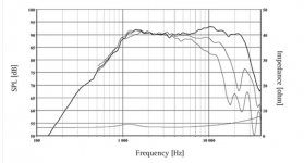
Here we have two 4 ohm tweeters in series and I entered 8 Ohms across the board. However, that electrical HP filter curve just breaks at some point (based on the measurement after the Xover) and that effect is completely missing in the sftw. So I am thinking the impedance measurement may be necessary this time. Else this is what I see in the sftw for the overall SPL summation with and without the tweeter inverted. Also attached is Seas spec for the 27TFFnc/g tweeter.
Thus I usually take a shortcut: instead of measuring impedance I import into PCD sftw SPL/Voltage transfer functions (instead of just SPL). Consequently I do not bother to specify any physical offsets between the drivers (since SPL for each is already phase referenced to the input voltage); and I also got away (so far) with just entering nominal impedance (since SPL amplitude has been normalized per unit voltage).
Since SL crossed these drivers so well within their on axis SPL capability, and the impedance in the manufacturer's spec appears uneventful, I thought this simple approach would work again; (I still see no reason why it should not).
Here we have two 4 ohm tweeters in series and I entered 8 Ohms across the board. However, that electrical HP filter curve just breaks at some point (based on the measurement after the Xover) and that effect is completely missing in the sftw. So I am thinking the impedance measurement may be necessary this time. Else this is what I see in the sftw for the overall SPL summation with and without the tweeter inverted. Also attached is Seas spec for the 27TFFnc/g tweeter.
Attachments

Last edited:
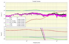
having thought about it some more, it looks to me that the likely cause is really the 2kHz resonance in the mid LP circuit rather than in the tweeter HP. it was harder to see in the previously posted plot but here on a linear scale it is a textbook 90deg phase shift under the peak.
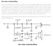
So before throwing an additional notch filter at it i decided to try and optimize the filter circuit a little better to iron up the impedance up to the Xover freq.
After playing a little more with the component values in the PCD I arrived at this filter which now looks better. Now I have to order the parts and test the Xover circuit. (shipping cost is a killer when doing iterations on a passive Xover)
Attachments

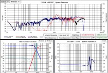

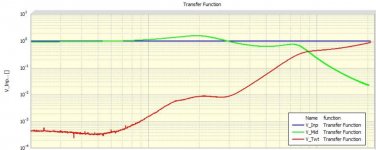
moded the Xover and retook the measurements. It confirmed that the phase tracking at the Xover frequency is now better. The mid response got a little bumped up on axis right before the Xover freq. Off axis all measurements look very good as a testament to SL having done an excellent work on the driver/baffle combination.
The only real issue is still that 1.9kHz resonance which causes the mid output to go over input and then under input at 5kHz. An additional 3 component wideband notch filter would probably sort that out. However, after I calculated the values for that filter, the cap came at 30uF which would be an electrolitic one.
I concluded that it does not make sense to iron out the curve in additional passive components when the filter characteristic to correct for is now a known (measured) curve and an active EQ is available and will be used, (since the low Xover to bass will be done with a 2x4 miniDSP). So I decided not to bother with a month worth of work to get an ideal characteristic passively but to EQ that out later on in the sftw.
the filter and the responses look like this. (in SPL disregard that 10kHz noise coming from my measurement equipment). I can post the values of the LR4 filter later on.
Attachments
Thanks for your work on this Koja - I have been hoping for someone to do a LX521.2 as the cost of 8-10 channels of quality amplification is a barrier and requires more space.
Are you trying to replicate, or benchmark against, the latest MiniDSP files and ASP.4?
I own a pair of LX521 top baffles, so would like to also test your crossover.
What are the voltage rating for the 30uF capacitor you need? Would a 30uF Mundorf Tube cap suit?
Are you trying to replicate, or benchmark against, the latest MiniDSP files and ASP.4?
I own a pair of LX521 top baffles, so would like to also test your crossover.
What are the voltage rating for the 30uF capacitor you need? Would a 30uF Mundorf Tube cap suit?
Last edited:
OK - Just found this very useful article... so perhaps you where right to stop development when you did.
In Pursuit of a 20-20k Dipole Loudspeaker
In Pursuit of a 20-20k Dipole Loudspeaker
Actually, an "LX521.2" (if you want to call it that) is something I've had on the drawing board for quite awhile. Only recently have I constructed some prototypes and have them playing.
Although, I've gone about it in a different way than what's outlined here by Koja.
Dave.
Although, I've gone about it in a different way than what's outlined here by Koja.
Dave.
Hi Davey - good to know. I'm a member on Oplug too. Where are you going to publish your findings?
I think CharlieLaub raises some good points in his paper so am interested in your approach. I have a pair of ncore monoblocks, so would have sufficient power - but the issue of loss of sensitivity due to a potentially complicated crossover design is an issue that interests me. I guess higher end parts (e.g. Mundorf Supreme) could be used to counter any losses once prototyped.
Watching with great interest 🙂
Most losses come from huge coils needed for dipole loss eq. Translam and motor coils have lowest DCR, but not what some call "hifi"
Solid Core Inductor Crossover Coils - Parts Express
Are you going for all-passive or leave the double woofers active? My guess is that mmt section must have some delay to the woofer.
Solid Core Inductor Crossover Coils - Parts Express
Are you going for all-passive or leave the double woofers active? My guess is that mmt section must have some delay to the woofer.
there is no significant resistance i.e. gain losses associated with this Xover since the coils are small. I have them in AWG18 wire and the Rs are on the order of 0.2 ohms or less. I will post the component values probably this weekend.
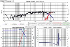
Crossing the upper mid to tweet has been realized with no issues. With the 2nd iteration I got a nice symmetrical notch with inverted tweeter measurements. So that part was textbook.
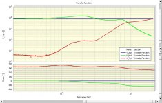
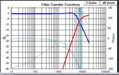
As already pointed out: the only issue is the wavy green line in Xover voltage measurements BELOW the Xover frequency. One would want a flat line close to ratio 1 (which is 10 to the power of 0 on that graph scale) i.e. input voltage at all frequencies below the Xover going through the circuit unaffected. So one would expect a flat line like the blue line in the modeled Xover in PCD software. I reattached the 2 graphs for you.
Due to some electrical interactions, adding the LR4 Xover in front of SL's 1st order (lower mid to upper mid) Xover, caused a clear resonance at 1.9kHz which produced this wavy gain characteristic which now has to be corrected for to get it back to flat.
Two choices here: (1) this could be done passively by adding another 3 components (LCR), or (2) the smarter approach (for me) is: since I am using miniDSP for bass-to-mid Xover I have EQ capability and will enter in miniDSP software a wave which is the inverse of the green wave so the sum result after the Xover will be a flat response. If I am not lazy I may even verify that by taking voltage transfer function measurements with miniDSP EQ added.
Crossing the upper mid to tweet has been realized with no issues. With the 2nd iteration I got a nice symmetrical notch with inverted tweeter measurements. So that part was textbook.
As already pointed out: the only issue is the wavy green line in Xover voltage measurements BELOW the Xover frequency. One would want a flat line close to ratio 1 (which is 10 to the power of 0 on that graph scale) i.e. input voltage at all frequencies below the Xover going through the circuit unaffected. So one would expect a flat line like the blue line in the modeled Xover in PCD software. I reattached the 2 graphs for you.
Due to some electrical interactions, adding the LR4 Xover in front of SL's 1st order (lower mid to upper mid) Xover, caused a clear resonance at 1.9kHz which produced this wavy gain characteristic which now has to be corrected for to get it back to flat.
Two choices here: (1) this could be done passively by adding another 3 components (LCR), or (2) the smarter approach (for me) is: since I am using miniDSP for bass-to-mid Xover I have EQ capability and will enter in miniDSP software a wave which is the inverse of the green wave so the sum result after the Xover will be a flat response. If I am not lazy I may even verify that by taking voltage transfer function measurements with miniDSP EQ added.
Attachments
there is no significant resistance i.e. gain losses associated with this Xover since the coils are small. I have them in AWG18 wire and the Rs are on the order of 0.2 ohms or less. I will post the component values probably this weekend.
Crossing the upper mid to tweet has been realized with no issues. With the 2nd iteration I got a nice symmetrical notch with inverted tweeter measurements. So that part was textbook.
As already pointed out: the only issue is the wavy green line in Xover voltage measurements BELOW the Xover frequency. One would want a flat line close to ratio 1 (which is 10 to the power of 0 on that graph scale) i.e. input voltage at all frequencies below the Xover going through the circuit unaffected. So one would expect a flat line like the blue line in the modeled Xover in PCD software. I reattached the 2 graphs for you.
Due to some electrical interactions, adding the LR4 Xover in front of SL's 1st order (lower mid to upper mid) Xover, caused a clear resonance at 1.9kHz which produced this wavy gain characteristic which now has to be corrected for to get it back to flat.
Two choices here: (1) this could be done passively by adding another 3 components (LCR), or (2) the smarter approach (for me) is: since I am using miniDSP for bass-to-mid Xover I have EQ capability and will enter in miniDSP software a wave which is the inverse of the green wave so the sum result after the Xover will be a flat response. If I am not lazy I may even verify that by taking voltage transfer function measurements with miniDSP EQ added.
Excellent strategy and what I would do if I had the skills and time to make a passive crossover. Perhaps once you’re happy you could share the layout as well as the component values.
Last edited:
I would not mind if some of the existing LX521 owners got involved with the passive Xover to help evaluate it. A group effort would be nice.
Like I said, if the LR4 Xover left the curve flat at lower frequencies it would have been a no brainer. The tweeters do not handle much to begin with.
p.s. Siegfried sort of jinxed it when he told me to not forget to take measurements due to possible interactions. I guess this is an example why doing passive Xovers in a 4-way design with a lot of overlap will never be simple.
With EQ I can get it back to flat on axis. The problem is that SL actually targeted an EQ out of flat on axis, and to get that will be more complicated.
I will start with flat first because I will have different bass units (sealed) and then work from there. I may try something close to what he was proposing even though I cannot say that I fully understand his reasons, (and he is no longer available to ask 🙁 RIP). Some noticed the LX521 midbass bloom so his EQ may be reflective of his personal taste (not to say that it is bad). I imagine he was designing exclusively for off axis performance in his room.
Last edited:
I'm not sure what there is to evaluate here. Unless a person is interested in altering the LR4 alignment this is essentially a mechanical process in curve matching. Since this is such a high frequency crossover with no shaping required the result should sound pretty much identical to the original (active) version. So, yes, you've saved two amplifier channels, but you've added quite a few passive components to the crossover stew.
The woofer/mid crossover is straightforward. That crossover requires extensive equalization....especially in the woofer portion....so it makes zero sense to attempt to address that via a non-multi-amp scheme.
By far the most interesting aspect (crossover wise) of the LX521 design is the midrange crossover. There you have two drivers where the objective was to blend them seamlessly over a wide range. That goal is certainly achieved, but at the expense of a couple of trade-offs that some users raised their eyebrows at. (Notably John Kreskovsky a number of years ago.)
The LM/UM crossover had a couple of versions depending upon the Revision of LX521, but they're all essentially the same thing. UM driver with a very shallow-slope HP, and a LM driver with a very shallow-slope LP.
This is where the experimentation should take place in the LX521
A "hybrid" scheme utilizing just four amplifier channels (total) is possible, and that's what I have playing in the listening room now. It sounds excellent. But I'm still putzing around with it.
Dave.
Dave - what were the trade offs that John Kreskovsky highlighted? As well as the ability to just run 4 channels of amplification, I am also very interested in being able to use a standard 2 channel DAC/preamp, this is also my attraction to the ASP.4 solution. As it would enable easier update and modernise the system (e.g bitrates above what MiniDSP can do). Signal to the woofers is probably always best to do via MiniDSP, as room compensation would also be possible and bitrate doesn’t matter as much <200Hz.
I own LX521 licence so can test collaboratively and also work through oplug
I own LX521 licence so can test collaboratively and also work through oplug
- Home
- Loudspeakers
- Multi-Way
- Crossover for Linkwitz LX521