Hi Elbert
Βravo you did well and found a solution to your problem
Persistence and patience are good tools.
What transistor you use BC546 556 OR BC550 560 (T1T2T3T4)
If you have the opportunity you have to do some tests with a generator and oscilloscope with dummy load .
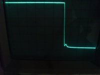
In my own amp I have a small problem in the square waveform.
What causes break in the corner On the negative side waveform?
AndrewT ,Bonsai any advice ?
Best regards Nikos.
Βravo you did well and found a solution to your problem
Persistence and patience are good tools.
What transistor you use BC546 556 OR BC550 560 (T1T2T3T4)
If you have the opportunity you have to do some tests with a generator and oscilloscope with dummy load .
In my own amp I have a small problem in the square waveform.
What causes break in the corner On the negative side waveform?
AndrewT ,Bonsai any advice ?
Best regards Nikos.
Attachments


Last edited:
Nikosokey, can you tell us what pk voltage these signals are taken at?
One other test you need to do here is to drive the amp so that it clips - just enought so the top 15-20% of the waveform is flat - and then also post a picture. You should do this test with no load, or a very light load (like 20 Ohms to 100 Ohms)
One other test you need to do here is to drive the amp so that it clips - just enought so the top 15-20% of the waveform is flat - and then also post a picture. You should do this test with no load, or a very light load (like 20 Ohms to 100 Ohms)
Hi Bonsai
Although these measurements are loaded. Do not remember exactly the value pk
with 8 ohm load and sine wave 1,1 rms input before the clip i measure 27 volts rms
Tomorrow I will I will give accurate values pk and from which point starts to break the square wave .
Thanks for the response to my problem
Nikos
Hi Nikos,
it's your turn to teach me.
I have no idea where to look for a circuit problem to eliminate that -ve wiggle.
it's your turn to teach me.
I have no idea where to look for a circuit problem to eliminate that -ve wiggle.
That must be great speakers to own and listen to! 🙂
Considering the amplifier you have buildt, I was allmost a bit surprised that you didn't have some wild DIY speakers, but then again, building, developing and testing serious loudspeakers is a bit different than electronic circuits!
Considering the amplifier you have buildt, I was allmost a bit surprised that you didn't have some wild DIY speakers, but then again, building, developing and testing serious loudspeakers is a bit different than electronic circuits!
Thank you Nikosokey!
I stayed with the BC 556/546 transistors for T1-T2.
Well, It so happens that I have a scope and know how to use it (!).
I even have a home made function generator which I can squeeze square-waves out of, so I'll see if I can do a dummy-load set-up to compare With your findings.
Not sure I have a 8 ohm resistor that can take the full load, but I'll see what I can do one of these afternoons!
Hi Elbert
Βravo you did well and found a solution to your problem
Persistence and patience are good tools.
Indeed, well done for keeping at it. Through perseverance you find a solution and often whilst learning something too.
I once had a similar problem although entirely my own fault. I couldn't get this circuit to work whatever I tried, then I looked once again the datasheet and saw in small print - *as viewed from below* - DOH! So I reversed the pin out and boom, it worked.😀
Hi Nikosokey,
we need to determine whther this is a 'sticky rail' problem or something else. This is why you need to do the sine wave clip test. If it is sticking on the -ve rail, then that issue needs to be fixed first. If it s not 'sticky rail' we have to look for some other mechanism. Here, I would favour disconnecting the output stage and taking feedback off the VAS to isolate the problem to either the front end or the output stage
we need to determine whther this is a 'sticky rail' problem or something else. This is why you need to do the sine wave clip test. If it is sticking on the -ve rail, then that issue needs to be fixed first. If it s not 'sticky rail' we have to look for some other mechanism. Here, I would favour disconnecting the output stage and taking feedback off the VAS to isolate the problem to either the front end or the output stage
AndrewT
(((Hi Nikos,
it's your turn to teach me.)))
AndrewT has a great sense of humor.
I have read many of your own post and learn from you as well as from other members.
Elbert
Ιt would be good to test your amp with the waveform and see the results.
What brand is your transistors bc546 bc556 Philips, On Semi,Motorola. ?
Bonsai
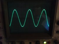
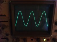
this is the result 1KHZ before clipping a sine wave does not see problem with rail +/ -
Ι will isolate the voltage amplifier from the LTP and see if it gives the same results (-ve wiggle)
What is the maximum input voltage waveform into squares that will be put?
1.1KHZ Max Vp-p=44volt.JPG
2.1kHZ before clip.JPG
3.1KHZ.JPG
Thanks for your advice.
(((Hi Nikos,
it's your turn to teach me.)))
AndrewT has a great sense of humor.
I have read many of your own post and learn from you as well as from other members.
Elbert
Ιt would be good to test your amp with the waveform and see the results.
What brand is your transistors bc546 bc556 Philips, On Semi,Motorola. ?
Bonsai
this is the result 1KHZ before clipping a sine wave does not see problem with rail +/ -
Ι will isolate the voltage amplifier from the LTP and see if it gives the same results (-ve wiggle)
What is the maximum input voltage waveform into squares that will be put?
1.1KHZ Max Vp-p=44volt.JPG
2.1kHZ before clip.JPG
3.1KHZ.JPG
Thanks for your advice.
Attachments
Last edited:
Nikosokey, you need to drive the amplifer a bit harder. The top 10-15% should be flat, and the rest of the wavefoem like a sign wave. This means, if the input sensitivity for your amp is say1V for full output, feed 1.1-1.2V in.
What we are looking for here ideally is that the amp comes out of clipping cleanly, with no rail sticking or parasitic oscillations.
You should do this first.
What we are looking for here ideally is that the amp comes out of clipping cleanly, with no rail sticking or parasitic oscillations.
You should do this first.
Nikosokey,
Bit of bad luck here I'm afraid.. turned out the batteries in my function generator were flat! 🙁
The best I can di in terms of load resistor is 16 Ohms. Will this load the amp sufficiently for me to replicate a measurement that gives meaningfull comparison to your results?
I have absolutely no idea what make the BC556/ 546 transistors I used are.
Checked at the website of our big scandinavina electronics distributor (Elfa, comparable to RS and Farnell etc..), and the transistors they sold were not identified in terms of brand, just that their country of origin was Hong-kong..
Speaking of these transistors.. I remember you used BC 560/550 for the T1-4.. These have a lower maximum voltage than the BC556/ 546 originally specified, perhaps this could explain the results you are seeing??
Seems It's difficult to obtain discrete semiconductors of known origin these days, be it from reputable distributors or random e-bay sellers.. 🙁
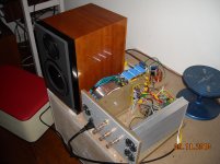
Hooked the amp to a loudspeaker today, and it plays music!
Not to easy to properly judge the sonic impression as I was only playing on one channel on a loudspeaker that only has a provisional passive X-over. (in anticipation of active set-up). But compared to the old NAD 3240PE, the sound seemed more open and with a tighter grip on the lower notes.
It will be interesting to hear what this will be like once the project is complete with all channels completed and active X-over properly adjusted.. not to mention the two subs I'm going to build in addition to the 2-way stereo speakers! 🙂
Bit of bad luck here I'm afraid.. turned out the batteries in my function generator were flat! 🙁
The best I can di in terms of load resistor is 16 Ohms. Will this load the amp sufficiently for me to replicate a measurement that gives meaningfull comparison to your results?
I have absolutely no idea what make the BC556/ 546 transistors I used are.
Checked at the website of our big scandinavina electronics distributor (Elfa, comparable to RS and Farnell etc..), and the transistors they sold were not identified in terms of brand, just that their country of origin was Hong-kong..
Speaking of these transistors.. I remember you used BC 560/550 for the T1-4.. These have a lower maximum voltage than the BC556/ 546 originally specified, perhaps this could explain the results you are seeing??
Seems It's difficult to obtain discrete semiconductors of known origin these days, be it from reputable distributors or random e-bay sellers.. 🙁
Hooked the amp to a loudspeaker today, and it plays music!
Not to easy to properly judge the sonic impression as I was only playing on one channel on a loudspeaker that only has a provisional passive X-over. (in anticipation of active set-up). But compared to the old NAD 3240PE, the sound seemed more open and with a tighter grip on the lower notes.
It will be interesting to hear what this will be like once the project is complete with all channels completed and active X-over properly adjusted.. not to mention the two subs I'm going to build in addition to the 2-way stereo speakers! 🙂
Last edited:
Ηι Εlbert
Everything looks good.
Reminded me please what is the value of the offset voltage without the op177 onto the board?
Nikos.
Everything looks good.
Reminded me please what is the value of the offset voltage without the op177 onto the board?
Nikos.
Nikosokey,
The output offset value I got whith the servo disconnected was about 0,6V (after I fixed the problem).
The output offset value I got whith the servo disconnected was about 0,6V (after I fixed the problem).
Εlbert
You are lucky to have found 546 556 fit so well.
Each amplifier presents its own characteristics.But the performance in RMS volts should be more less the same if compared with the same load and the same value in volts input.
You are lucky to have found 546 556 fit so well.
Each amplifier presents its own characteristics.But the performance in RMS volts should be more less the same if compared with the same load and the same value in volts input.
First live test! 🙂
That looks like a SEAS DXT tweeter with some midbass I can't identify. Love the DXT myself.
Yes, that is in deed the SEAS DXT tweeter. So far I'm only running it with a simple x-over, so I really look forward to filtering it propperly and get a flat curve!
The midbass is allso a SEAS, a W17CY001. This is an excell woofer with glass-fibre diaphragm. It is officially obsolete, but the local dealer found out that SEAS had a batch of newly manufactured units in stock,and I was able to pick up a cople of those,, at a price of course. They probably did a limited production run for a customer or something.
Nikosokey,
Got some fresh batteries for the function generator today!
I hooked the amp up with the generator and a 16 ohm load on the output.
I then adjusted the generator to 1 KHz sine wave and 1V, and switched the amp on.
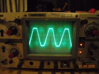
Got a nice clean sine wave on the scope showing 40v peak-to peak.
I then cranked the generator as far as it would go, and that gave me a waveform as you can see on the attached picture.
Not the square like scope-image you got, so obviously, my generator was not able to drive the amp to the same level of clipping.
The picture is not the best, and the scope is not state of the art, but I could see no sign of similarities to the waveform you got.
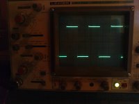
Just out of curiosity, I decided to feed the amp with some square waves just to see what happened..
On the positive flank, the signal rises sharply, then dropps back before rising again to full level with a rounded off waveform. There is allso a rounding off of the waveform at the bottom of the negative flank.
The rounding off seems to match the waveform comming out of the generator, but that spike.. what could that be??
Is this what the amp will normally do with square waves, or is this an indication of something not being quite right??
The midbass is allso a SEAS, a W17CY001. This is an excell woofer with glass-fibre diaphragm. It is officially obsolete, but the local dealer found out that SEAS had a batch of newly manufactured units in stock,and I was able to pick up a cople of those,, at a price of course. They probably did a limited production run for a customer or something.
Nikosokey,
Got some fresh batteries for the function generator today!
I hooked the amp up with the generator and a 16 ohm load on the output.
I then adjusted the generator to 1 KHz sine wave and 1V, and switched the amp on.
Got a nice clean sine wave on the scope showing 40v peak-to peak.
I then cranked the generator as far as it would go, and that gave me a waveform as you can see on the attached picture.
Not the square like scope-image you got, so obviously, my generator was not able to drive the amp to the same level of clipping.
The picture is not the best, and the scope is not state of the art, but I could see no sign of similarities to the waveform you got.
Just out of curiosity, I decided to feed the amp with some square waves just to see what happened..
On the positive flank, the signal rises sharply, then dropps back before rising again to full level with a rounded off waveform. There is allso a rounding off of the waveform at the bottom of the negative flank.
The rounding off seems to match the waveform comming out of the generator, but that spike.. what could that be??
Is this what the amp will normally do with square waves, or is this an indication of something not being quite right??
Attachments

Well, looks like I found the explanation for that square wave spike..
Went back and decreased the level of the signal, and then got a waveform exactly like that comming out of the generator. I then increased the signal level further and at one point, I could se that spike starting to materialize as a small disturbanse in the rising flank. I then cranked the signal up further..
The peak voltage didn't increase, but the spike grew and soon after it became fairly pronounced, the protection relays clicked.
So it seems I was only driving the amp harder than it liked to be driven with square wave food.
post 198 shows a clipped sinewaye.
It shows the recovery from clipping to be clean. As far as the pic shows.
Is it clean in real life? Turn your spot brightness down a little.
A squarewave signal that asks the amplifier for way more than it is capable provides me with no useful information. Attenuating the test signal would have been a lot more helpful. Start with a low level signal (maybe -40dB ref max power) and increase in steps until something odd in the output appears. Is that oddness due to severe overloading or due to a circuit "fault"?
- Status
- Not open for further replies.
- Home
- Amplifiers
- Solid State
- Crescendo Millennium offset problem