Hi All,
I'm trying to figure out if I should replace the paired transistors in my amp according to the schematic or stock. I noticed the transistors on my Destiny are printed with 3B and 1B, which are BC856B and BC846B. While the schematic lists BC856C and BC846C. The twist is I've also found a close up photo of another Destiny that has markings 8AC and 9AC (BC856C and BC846C) on those same transistors. The only difference between group C and B that I can determine is the hFE values. Are there any sonic differences I might encounter with one versus the other in this stage of the amp? Does the different hFE apply in the circuit? Do I follow the schematic? The BC856Cs and BC846Cs are difficult to find but available through Diotec, a marketplace seller on Digikey. Any help is appreciated.
I'm trying to figure out if I should replace the paired transistors in my amp according to the schematic or stock. I noticed the transistors on my Destiny are printed with 3B and 1B, which are BC856B and BC846B. While the schematic lists BC856C and BC846C. The twist is I've also found a close up photo of another Destiny that has markings 8AC and 9AC (BC856C and BC846C) on those same transistors. The only difference between group C and B that I can determine is the hFE values. Are there any sonic differences I might encounter with one versus the other in this stage of the amp? Does the different hFE apply in the circuit? Do I follow the schematic? The BC856Cs and BC846Cs are difficult to find but available through Diotec, a marketplace seller on Digikey. Any help is appreciated.
Attachments
-
 Screen Shot 2021-12-07 at 2.22.35 AM.png670.3 KB · Views: 501
 -
 Screen Shot 2021-12-07 at 2.23.43 AM.png428.5 KB · Views: 543
 -
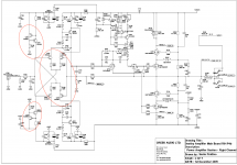
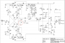
Destiny Amp R01 P4B Main Board.pdf415.5 KB · Views: 254
-
BC856B_Nexperia.pdf205.7 KB · Views: 177
-
bc856C_Diotec.pdf141.6 KB · Views: 135
-
 Screen Shot 2021-12-07 at 2.41.42 AM.png218 KB · Views: 657
Last edited:
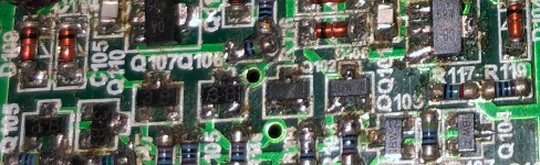
Don't know why you want to change input stage transistors. Are they burned up? Fail the double diode test? Make sizzling or popping noises? That left board has a bad case of burned flux, it appears to me. Alcohol & a good scrub come first, IMHO. If the board was burned through by some cataclism, no amount of cleaning will stop carbon from shorting out. New PCB required.
Low hanging fruit in a 20 year old amp is C107, C109, C111. Date on the drawing is 2005, not that long ago. Other high failure parts are zener diodes like the couple of ZD's you've got.
Yes, input transistors are selected for high gain & quietness. I found of a hundred On Semi TO-92's I bought for $9 in 2013 the gain was about 300 and the quietness put them right in the range of BC557C without the datasheet guarentee. Processes are more under control now than 1978. No hair or skin flakes in the fab area. No humans allowed except maintenance men in bunny suits. I haven't bought any modern oriental commodity parts. No knowledge if the clone fabs are as careful with such consistent product.
There are tons of surface mount transistors available. Digikey wasn't much help, the only single transistors that came up on the first chart were fet dies. However newark the selector table when set to bjt and 250mw to 800 mw and surface mount came up with hundreds of offerings. I tend to set Vceo >50 for audio products and avoid ones where the datasheet says switching transistor, but if the intended use is amplifier I wouldn't imagine an exact number match buys you anything. Gains over 100 should be economically available.
Last edited:
Hi,
Thanks for the response. What is the harm in replacing those transistors if at least for the sake of inexpensive preventative maintenance? I've already replaced all the diodes and electrolytic caps. I've also cleaned more of the burned flux. I am suspicious there is an issue in the right channel because dc offset is very jumpy after warming up (I've replaced the dc servo components), yet still below 10mV. The amp has a long history of damage from yours truly, I've shorted some components, over biased the output devices etc. It also an unknown history and bought for parts. I am trying to find out in this particular circuit will there be a sonic difference between using lower gain (~220) transistors which are stock in my case, or the higher gain (~420) ones that are in the schematic, and the other Destiny.
Thanks for the response. What is the harm in replacing those transistors if at least for the sake of inexpensive preventative maintenance? I've already replaced all the diodes and electrolytic caps. I've also cleaned more of the burned flux. I am suspicious there is an issue in the right channel because dc offset is very jumpy after warming up (I've replaced the dc servo components), yet still below 10mV. The amp has a long history of damage from yours truly, I've shorted some components, over biased the output devices etc. It also an unknown history and bought for parts. I am trying to find out in this particular circuit will there be a sonic difference between using lower gain (~220) transistors which are stock in my case, or the higher gain (~420) ones that are in the schematic, and the other Destiny.
Last edited:
Total wasted effort. Transistor fail because of thermal cycles stressing the bond wires, and input stage transistors don't heat up. Some transistors are overstressed by too much leakage current from over-voltage. I don't see any sign of that here. Output transistors & drivers fail because too much current went out the speaker jack, likely a shorted 1/4 phone plug 1/4" out, or a shorted turn in a speakers coil, or an errant wire. Input parts fail in those circumstances because rail voltage blows out the base wires of the shorted outputs and drivers and blasts into territory where the voltage ratings are not that high. Filter caps and resistors go in the total meltdowns caused by shorted speaker terminals.Thanks for the response. What is the harm in replacing those transistors if at least for the sake of inexpensive preventative maintenance?
Higher gain input transistors lower the current required in the input jack from the source, a preamp, radio, mp3 player, whatever. I knew about the MPS8099 gain because I had to redesign an AX6 board to be compatible with a 1961 PAS2 preamp, that can source total of 2 ma from the plate of a 12AX7 vacuum tube. Most modern devices are 600 ohm drive, can source 25 ma. My most recent purchase, a QSC CX302, only has 6000 ohm input impedance in bridge mode. My modified AX6 board is ~100000 ohms.
Creek likely subjected the original input transistors to a incoming inspection of gain & noise. If you buy some from a distributor, you don't have the equipment to do that. If you buy some from some shady source, likely you'll get counterfeit, or at best pn2222 dressed up with a fancy number.
I use 1970 input VAS & driver transistors on a board in one of my amps. One side blew everything back to the input transistor, the other side everything but the output transistors was okay. No problems. In fact the 1970 drivers 2n5322 2n5320 had better sound than the TIP31c/32c I used as drivers on the blown side. Higher Ft. I had to go back and replace the TIP drivers with MJE15028/29 to equal the sound on top octave steinway piano and tinkly bells.
Last edited:
Thank you for all of the information. I have much to be mindful about going forward, and yes hindsight is 20/20. Can a faulty transistor in this input stage cause dc offset spikes? I’ve ordered those Nexperia bc846b and bc856b pairs with some capacitors for another project from Digi-Key. Regardless will do more research before diving into changing these transistors.
DC offset spikes in the output are more likely an adjustment pot somewhere, losing wiper contact. Or a part in a dc servo circuit losing internal contact or contact with PCB (bad joint) and causing jumping. I don't see any adjustment pots on this schematic and I don't see a DC servo either. Bad solder joints or bad internal weld can affect any part, resistor, capacitor, diode, transistor. Resistor is most likely for bad internal weld I read, they sell for about $.003 in thousands. Need to set up a scope to trigger on small DC shifts and see how far forwards from output you can go before the DC jumps stop. Or if no DC stable scope ( I don't have one) set a comparitor to detect small shifts then to fire a pulse stretcher that drives a LED if a DC shift occurs. A lot cheaper than a Tek 475 but more engineering involved. Between the place where the DC jumps stop and the output is where the problem is. Short the input while patrolling for random DC jumps.
Edit, that brown crud all over the left PCB is a likely culprit for temporary mystery shorts. I replaced an organ that made rude noises about once an hour on humid days. 57 years of dust on those 300 v chassis, and I didn't want to spend 40 hours cleaning it. Moisture + dust = carbon tracks. If the brown is burnt into the PCB, call it a loss. Nothing dissolves carbon.
Edit, that brown crud all over the left PCB is a likely culprit for temporary mystery shorts. I replaced an organ that made rude noises about once an hour on humid days. 57 years of dust on those 300 v chassis, and I didn't want to spend 40 hours cleaning it. Moisture + dust = carbon tracks. If the brown is burnt into the PCB, call it a loss. Nothing dissolves carbon.
Last edited:
Ok will see how much more I can clean and look for contact issues. There is a dc servo, ill check that again. The dc servo schematic is in the amp schematic attachment I uploaded. There are some inexpensive (under $100) handheld oscilloscopes I’ve been looking at buying for repairs. Thanks. Yes there’s much to troubleshoot before those input transistors, would be a shame to replace those and have bigger issues. Interesting story about the organ! Thank you for the help.
Last edited:
There are indeed cheapo oscilloscopes and even assembly kits, if you enjoy that sort of thing. The question is, how good is the screen resolution and capture on such tiny and low-res screens? My personal experience is that for audio, these mini-scopes are OK for looking at steady state tones and what is obvious also by simple measurements but for many transient signals, they give inconclusive or simply invisible results because of low bandwidth and resolution failings.
There are also some high quality, handheld, multimeter styled miniscopes too. Useful ones are generally for pro. use in checking power distribution systems but not cheap at all, considering that you can buy a full sized (175mm screen) and full featured, 50-100MHz scope for (occasionally) much less than £200. Don't forget that wide bandwidth is important with 'scopes because the harmonics, noise and glitches you are looking for, happen to contain much higher frequencies too. So for any accuracy, bandwidth often needs to be at least two orders higher than the fundamental frequencies of interest. 100MHz bandwidth does seem unnecessary for audio but you often need at least 20MHz bandwidth for serious problems, should your interest in audio take you beyond just replacing parts on suspicion that what the manufacturer fitted wasn't up to their own spec. Detecting Oscillation that can exceed 30 MHz in mosfet amplifier designs for example, can require some decent gear to identify.
Regarding input pair transistors, I also sometimes find what superficially are noisier devices than the types specified on the original or an earlier issue schematic. There are manufacturing reasons for this and one is that the performance of the lower spec devices when actually produced, may overlap or even exceed that of the original design spec. device. If the original spec parts aren't available at the time of the amplifier's production, there are compelling reasons to substitute with what meets the spec of the original semi and equally, maintains the overall amplifier within specs. Noise specs aren't easy to understand either. A simplistic comparison of NF numbers doesn't address what you might think and just swapping better spec'ed transistors may do nothing or even make things a little worse. Much depends on the conditions of use - bias current, circuit voltages and bandwidth etc. of the application. Also for interest, take a look at the noise performance curves of early low noise semis, as once included on OEM datasheets for small signal devices like BC109, 149, 549 and so on.
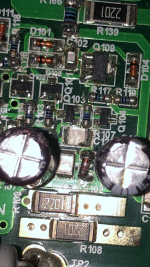
Thanks for both of your in depth and helpful replies. I've decided to leave the transistors alone, and I'm going to hold off on buying an oscilloscope since I'm not sure about the scope of my repair as a hobbyist. I recently used an inexpensive handheld oscilloscope for making quartz turntable adjustments to factory specs in the kHz range. Anyhow I am glad I didn't jump the gun replacing the input transistors and instead returned to troubleshooting. As it turns out after more cleaning, replacing all the zener diodes, and touching up connections solder in the DC servo the right channel DC offset is more stable (fluctuates within +/-5mV ), left channel DC offset seems to be remarkably low and stable at .5mV (+/- .2mV). Unfortunately upon powering up the amp went into fault mode because of a damaged MLCC (C19) in the Left channel DC servo and current sense power supply circuit (the power supply voltage had dropped from 15 to 10 volts). Luckily, I had a an extra used MLCC lying around as a temporary replacement. Note! I cleaned that MLCC which had a small chip in the terminal to ceramic boundary with IPA and that probably caused it to break down more lol. Double Note! Most of the repairs I am now making are from my own shoddy workmanship! Proper tools, technique and a clean board are essential! I also noticed another MLCC (C125) in the right channel that has small chip in the corner which I plan to replace.
Is a fluctuating DC offset +/5 mV (within a few seconds) something to be concerned about?
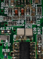
Does voltage across R5 and R105 play a role in the DC offset for the respective channels? It looks like this voltage shows how well balanced each channel is.
As it turns out
R105 = 4-5mV
R5 = 1-2mV
Is a fluctuating DC offset +/5 mV (within a few seconds) something to be concerned about?
Does voltage across R5 and R105 play a role in the DC offset for the respective channels? It looks like this voltage shows how well balanced each channel is.
As it turns out
R105 = 4-5mV
R5 = 1-2mV
Attachments
Last edited:
I can't spot R105. If 5 mv pulse is getting out to the speaker jack:
I listen to soft music at about 1.5 vpp into 8 ohm speakers of sensitivity 101 db 1w1m. That is ~0.5 Vrms. db-=20log(v1/v2) so 20*(-2) =-40 db. 5 mv DC shift could be audible 40 db down from music. During silence between tracks the audibility would be worse.
I listen to soft music at about 1.5 vpp into 8 ohm speakers of sensitivity 101 db 1w1m. That is ~0.5 Vrms. db-=20log(v1/v2) so 20*(-2) =-40 db. 5 mv DC shift could be audible 40 db down from music. During silence between tracks the audibility would be worse.
R105 is in the red circle of the screenshot I uploaded. Thanks! 40 db down from soft music puts things into perspective! So its virtually inaudible. My concern is those fluctuations are from a failing component, or if they're expected with a dc servo.
I circled the actual capacitor in yellow. The label C125 is partially blocked by the tower capacitor in the photo.

Here are videos I took of dc offset for 30 seconds after warming up for an hour. No input selected. The left channel is very stable. However, I don’t know if the right still falls into what is expected for this circuit. I was considering replacing the transistors because I nearly replaced all of the other components on the board at the time. Replacing the transistors was a last ditch effort to remedy these dc offset fluctuations, and what I thought was a elusive shrillness in the right channel.
Honestly, I don’t know if that’s placebo effect! Thanks all for the help.
DC Offset R Channel
Left Channel
After recent work
Honestly, I don’t know if that’s placebo effect! Thanks all for the help.
DC Offset R Channel
Left Channel
After recent work
Last edited:
There's seldom any reason to ensure the DC offset at an amplifier's output is any lower than about +/- 30mV unless say, the amplifier is one of several in an active crossover speaker system, where all speaker drivers are connected directly to their separate, equalised power amps. In a multiway, passive crossover system, like most domestic loudspeakers, any slight displacement of the voice coil by a DC offset is often said to affect the operation of the tweeter and midrange drivers but these will be capacitively coupled, so its not likely to be the issue its made out to be.
Otherwise, it's commendable to have such low offsets if they remain so in use but don't sweat it because it really doesn't do much for regular speaker systems anyway. What you read as instability there though, could equally be called noise, considering how small a level that output is.
Otherwise, it's commendable to have such low offsets if they remain so in use but don't sweat it because it really doesn't do much for regular speaker systems anyway. What you read as instability there though, could equally be called noise, considering how small a level that output is.
Last edited:
Thank you, this is helpful information. I'm realizing there is at times many layers of information to learn before making any diy tweaks. I'll take less than 30mV as just fine. I checked and the DC Offsets in both channels stay within 5mV while playing music.
Back to transistors, I have another couple questions. In my repair journey I replaced the original HUF76639P3 MOSFETs output transistors with IRL2910s. I did not know about matching at the time and haven't experience any apparent negative effects. After browsing these forum sites it seems most of how to match information is on these very forum sites, and setting up a proper testing platform involves more than looking at the hFE values, but matching per hFE can be a bare minimum.
I did find a matched BC846 pair transistor by Nexperia. Is their criteria a good indicator of what is considered well-matched?
hFE1/HFE2 is .9
Vbe1/Vbe2 is 2mV.
Nexperia - https://www.nexperia.com/products/b...istors/matched-pair-transistors/BCM846BS.html
On the same token, regrading the single transistor like the BC846B, Nexperia publishes min, max, typical values for hFE and Vbe, but not tolerances... Is there a general idea of what the tolerances might be? The published min/max ratio is close to 50%!
Last edited:
Nexperia and Infinium (that's Philips and Siemens in old-speak) both make a number of similar dual transistors that are suitable for long-tailed pairs or LTP input stages (i.e. they're fabricated on the same or adjacent die). These will have good, practical matches in use. A perfect, hand matched pair of 2 discrete transistors once seemed to be an ideal arrangement but their temperatures and properties won't track as well as adjacent semis on the same die and its this close tracking that makes any match a realistic, affordable and useful proposition. Quoted matches will be bettered in like, 99% of examples so there's little need to sort or cherry-pick them.
The intrinsic match of a dual transistor will be all you need in a real amplifier as opposed to an idealised model that no one can produce and we could only imagine the benefits. Even that assumes it is always best to have a perfectly matched LTP. Personally, I think that makes home audio an intellectual pursuit that can get in the way of feeling the music as entertainment. 'Fine if you are happy just knowing that your amp has the lowest THD possible but this doesn't necessarily correlate with the best sound quality and entertainment value.
The intrinsic match of a dual transistor will be all you need in a real amplifier as opposed to an idealised model that no one can produce and we could only imagine the benefits. Even that assumes it is always best to have a perfectly matched LTP. Personally, I think that makes home audio an intellectual pursuit that can get in the way of feeling the music as entertainment. 'Fine if you are happy just knowing that your amp has the lowest THD possible but this doesn't necessarily correlate with the best sound quality and entertainment value.

Got it 🙂. I figured that’s what you meant. I have a friend who worked at Siemens back in the day. I’m going to let the transistors rest for a while. I couldn’t find a closely matched bc846/bc856 dual transistor. Anyway amp sounds wonderful. In regards to C125, It fell like a house of cards when I touched the iron to it. I’m guessing it was on the fritz and has been replaced. Replaced another questionable resistor and capacitor, and cleaned the dc servo. Now dc offset is around 5mV-7mV but more stable, hooray. Thanks again for the help.
Good that replacing the obvious damaged parts was effective - great result. If you want to follow up on transistor duals, you'll find they're all SMD now and BCM846 /BCM856 are the common reference part numbers. To proceed, you would likely need to buy a small qty of little SOIC8 adaptor boards (quite cheap from China) and wire them up in place of current semis . Its tiny and tedious work but quite doable. If you choose to
go ahead, I for one, would love to read your results with this amp or any other widely known, good sounding model.
go ahead, I for one, would love to read your results with this amp or any other widely known, good sounding model.
Thanks. The current transistors are actually smd. But I’m afraid desoldering them from the board will damage them. I found this dual transistor pair -Good that replacing the obvious damaged parts was effective - great result. If you want to follow up on transistor duals, you'll find they're all SMD now and BCM846 /BCM856 are the common reference part numbers. To proceed, you would likely need to buy a small qty of little SOIC8 adaptor boards (quite cheap from China) and wire them up in place of current semis . Its tiny and tedious work but quite doable. If you choose to
go ahead, I for one, would love to read your results with this amp or any other widely known, good sounding model.
https://www.mouser.com/ProductDetai...es/BC-846PN-H6327?qs=OWKQh20chuofpcTPNWX91g==
How do I know if even these are a well-matched NP pair? I found PP and NN data sheets with published HFe ratios. This datasheet doesn’t include those data points. Is it safe to assume they are well matched? Also, how do I wire from the transistor duals to the pcb pads? And there 4 NPN/PNP pairs to replace?
- Home
- Amplifiers
- Solid State
- Creek Destiny: Replacing transistors in amp stage