well those regulated rails are 25v, as i first suspected, the drawing is incorrect and if im right thats proberbly why it failed, the caps were only 25v.I uprated all caps to 35v
speaker terminals are at 0v
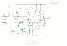
so just the bias, i assume it is done as attached
speaker terminals are at 0v
so just the bias, i assume it is done as attached
Attachments
im realy not sure how to do this as i dont trust any of the drawings at all.references are nothing like whats on the board, some values missing, and components that are different
i have -14mv on one channel and +14mv on the other channel
ive not plugged any speakers in yet.
one strange thing as well
if you turn the amp off and leave the bridge switch out the lamp comes on, then if you push the switch in it goes off, press it again, the lamp stays off.turn it off and lamp stays off when you turn it on again, unless you leave it a while and the lamp is on again untill you press the switch and the lamp goes off
could this be main filter caps?
so all is not as good as it seems
found one of the drivers gone and stripped down the heatsink to see what was what and there is a flash point near the driver so i checked it and it was blown
now i have replaced it the speaker terminal has 68mv on one channel, so a bit more investigation required tomorrow
all of the output resistors are buried underneath the heatsink
biggest issue is i dont have an accurate drawing to work with and to work on it properly and safely you have to remove the transformer to turn it over
its the last time i get one of these lol!! ,still its a bit of an experience,even if it is a bad one lol
Check the supplies on the opamps as they will be lower than -/+25. The 25 volt is unregulated, the regulated voltage (on the opamps) will be something like -/+16 volt.
So a bit of real fault finding awaits 😉
It is. The higher the pot resistance and the lower the bias current.so just the bias, i assume it is done as attached
Its all good experience. You've got comfortable with the NAD's. When faced with something like this its often easier just to dismantle the thing rather than wondering about to get at things.its the last time i get one of these lol!! ,still its a bit of an experience,even if it is a bad one lol
So a bit of real fault finding awaits 😉
Yeah you are right, but it makes you realise how poor some things are in design, well at least when it comes to repairs-you have to remove the transformer to work on it properly, so everytime you need to test anything you have to re assemble.
time to re invest in that besnch power supply i recon 😉
Im supprised electronic equipment doesnt come under the CDM regulations, as that specifies all parts must be readily accessable for maintenance purposes, but i guess this is different.
time to re invest in that besnch power supply i recon 😉
Im supprised electronic equipment doesnt come under the CDM regulations, as that specifies all parts must be readily accessable for maintenance purposes, but i guess this is different.
Offset is what it is but it should be low (again -/+100mv is a typical target value historically). It can be tweaked by transistor selection of the differential pair and trying different matched pairs.
You'll probably find its not that horrendous to work on once you get into it and do a bit of dismantling.
Have you got a simulation for this one? Can't remember if you have or not 🙂
You'll probably find its not that horrendous to work on once you get into it and do a bit of dismantling.
Have you got a simulation for this one? Can't remember if you have or not 🙂
I have one you did earlier, it's in the messages. Not getting any current readings across those 0.22ohm's.can I break the emmiter circuit and put a 1ohm in like I do on the other amps to do the current? I presume the principle is the same. I don't realy trust the drawings TBHOffset is what it is but it should be low (again -/+100mv is a typical target value historically). It can be tweaked by transistor selection of the differential pair and trying different matched pairs.
You'll probably find its not that horrendous to work on once you get into it and do a bit of dismantling.
Have you got a simulation for this one? Can't remember if you have or not 🙂
You can add a resistor but the 0.22 ohms are perfectly good enough. If you have no voltage across them then you have no current flowing. It doesn't really need proving by other means.
I would begin by looking at the voltage across TR4 (on the hand drawn image) and checking it increases as you alter the preset. You need around 2.5 volts across that transistor to begin to turn the outputs on.
I would begin by looking at the voltage across TR4 (on the hand drawn image) and checking it increases as you alter the preset. You need around 2.5 volts across that transistor to begin to turn the outputs on.
Fair enough, I did think that. I presume either one can be used, as there are 2,one on each rail
The simple answer is that either 0.22 ohm in a given channel can be used as they are effectively in series. So whatever you read across one resistor should be similar (although it won't be exactly the same) as the other.
Although I could dream up a scenario where that wouldn't hold true it would be really obscure.
Although I could dream up a scenario where that wouldn't hold true it would be really obscure.
so ive set the bias on both to around 31mv, so thats not a probel.I did find another transistor gone, but i still have this -68mv on the right speaker terminals, the other is -14mv
would you be happy with such a difference?
would you be happy to plug in with these figures?
would you be happy with such a difference?
would you be happy to plug in with these figures?
update
see attached
my only concern now, and ive not tried it on speakers yet, is the heatsink is pretty hot, not so you cant touch it, but pretty warm
thing is i dont know what is normal for these realy, so i think its time to maybe try it out
see attached
my only concern now, and ive not tried it on speakers yet, is the heatsink is pretty hot, not so you cant touch it, but pretty warm
thing is i dont know what is normal for these realy, so i think its time to maybe try it out
Attachments

further update.
been using it now for about 40 mins at reasonable volume and the heatsink is at 69c, but as i said i dont know what is normal
It does have thermal protection attached to the heatsink, so i imagine they anticipated it getting quite warm
sounds good though.
sound doesnt appear muddled as some amps do that i have listed to, not too bright and quite good bass, if a little sloppy
ill keep testing then check on the centre/current see how it is
so for now, music off and just leave to sit there
current has risen to 65mv on both channels
heatsink 70c
Last edited:
31mv across 0.22 ohm is 140 milliamps which is on the high side. An ideal current would be just over 100 milliamps but even then commercial constraints sometimes come into play and the recommended may lower still. I doubt you would hear any difference between 10 milliamps vs 100 milliamps.
So I would turn it don a little.
68 millivolt offset is perfectly fine. The current that causes to flow in an 8 ohm speaker is just 8.5 milliamps. If you swap the two transistors around in the differential pair you might find it makes it lower (or higher... you can't tell until you try).
So I would turn it don a little.
68 millivolt offset is perfectly fine. The current that causes to flow in an 8 ohm speaker is just 8.5 milliamps. If you swap the two transistors around in the differential pair you might find it makes it lower (or higher... you can't tell until you try).
my main concern is this
the heatsink temp continues to rise even though ive turned it off and it is now 76c, i personaly think that is higher than it should be.
the idle current is over 55mv and i set this at 31, as per the hand drawn drawing instructions
so ive turn it off to let it cool down, then have another look
another thing that still bothers me is sometimes when i turn it on the lamp comes on bright, but if you immediatly depress the split/intergrate switch at the back it goes off,depress it again and it stays off, so that cant be right
I have cleaned the switches
It sounds to high and to hot to me. Is TR4 in thermal contact with the heatsink so it can sense temperature and reduce bias current?
I would begin with a low value, say 10 millivolts across the 0.22 ohm which is 45 milliamps and see if the amp holds that value. If it rises then keep bringing it back down to 10 millivolts by readjustment.
Once it is steady then switch off and let it cool.
When cool switch on and see what the cold voltage is across the same 0.22 ohm. As long as it is a couple of millivolts or more when cold then its fine.
You will have to re adjust in the same way when finally on full mains.
The switch issue shouldn't directly affect things but its hard to say without seeing it all. If you have speakers connected then any sudden transient may draw current and light the bulb. Without speakers and I can't see how it could do anything really. I suppose we could really do with knowing how the switch is wired and what it actually does electrically. Bridging mode usually inverts one channel but does so at the power amp input (usually).
If the bulb stays lit when you operate the switch then I would say not normal, if it gives a flash then it may be fine.
Oops, I see Mooly has beaten me here - never mind for what its worth.....
The first 5050 schematic that you posted did describe the bias as 30-35 mA so it was sensible to observe that but did you reset it cold or after warm-up? If the bias keeps rising, it suggests you may need to reset it later, after warming up, rather than when cold or below normal operating temp. range.
You probably need to rest the cover back on it to speed the process up a bit. The small vent in the top of the case and small heatsink tells us its no powerhouse anyway but there is a perception among audio tinkers that more bias always sounds better - damn the torpedos. Unfortunately it also means a stronger chance of heat related failures in commercial designs where economies are necessary and corners are cut. Even thermal runaway can happen in exceptionally warm weather or climates.
so i let it go cold, turn it on and the current was +40mv so i have lowered it to 11 for now, and will re adjust once fully warmed up, say 10 mins
problem is on full mains you cant tell if the lamp is on or now?
problem is on full mains you cant tell if the lamp is on or now?
You have to be confident the amp is all OK before going to full mains. 11 millivolts is 50 milliamps so see what what it rises to when fully warm. In many ways setting the bias toward the lower end of what is acceptable is often better on commercial amps like these. Remember that on full mains the current may be higher and so will need tweaking back down.
- Home
- Amplifiers
- Solid State
- Creek 5050