You should be fine up to around 4 volts peak (8 volts peak to peak) which is 1 watt into an ohm load (for a sine). Any amp should cope with that for sine and square up to 20kHz.
You can find even at those levels that there is significant heat generated in output transistors if you leave it like that for many minutes. You will get a feel for it if you try it.
Set an amp up to give 1 watt into 8 ohm and see how warm the heatsink gets (or doesn't, it all depends on the amp and how much heatsinking there is). Trying things experimentally is all part of the learning.
At high frequency testing the Zobel network (the resistor part) starts to heat up and that is often not rated to cope with high level high frequency testing in a lot of amps. Remember that power is 'voltage squared' divided by R and so small increases in voltage mean the power dissipated starts to rise very quickly.
so I've not looked at the amp yet but something fizzed towards the rear of the amp.
I've looked and i had it set on about half way. The range is 0-20v@ 0db so it would have been about 10v 🙁
i imagine that's why it didn't like it!
I've looked and i had it set on about half way. The range is 0-20v@ 0db so it would have been about 10v 🙁
i imagine that's why it didn't like it!
That was on another amp though, not the Creek which isn't working at all. I'm just trying to keep up 🙂
Always monitor output with the scope when testing and keep the levels reasonable. The Zobel network sees the same power dissipation irrespective of whether you have a real load connected or not.
Always monitor output with the scope when testing and keep the levels reasonable. The Zobel network sees the same power dissipation irrespective of whether you have a real load connected or not.
what i meant to say was it was the NAD i blew up, the 3020i that i had just finished repairing sometime ago.
I already looked and can find nothing obvious, so I put it to one side for now, but I will go back to it👍I thought it was one of the NAD's. A nice easy one for the weekend then 😉
I've got the Creek to deal with and 30 others yet 😩
Yep 30.im not complaining as quite a few of them are from people who recommended me, so I'm quite chuffed at that TBHOK 🙂
(how many!)

before I start the replacement procedure in such cases the question rises up, why was happen this.Just received this unit that isn't working.
Just says 'not working' on it
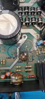
Anyway plugged it in and it started to smoke-rectifier melted and the left cap is very swollen.
According the images from post #9 it is for me clear, why; because the choice fell on weak versions for rectifier and electrolytics.
If the failure had occurred suddenly without previous permanent thermal stress, PCB area around this parts would not have been burned black.
In this case had been preceded by long-term thermal stress - thus it is not desirable to preserve the original condition.
This small round bridge rectifier I would replace by 4x 1N5408 without shorting the leads. Additional important is to remove the terminal block CTB2202/2 and replace by solder legs.
check also out also this thread:
https://www.diyaudio.com/community/threads/creek-5050-repair.309825/
Last edited:

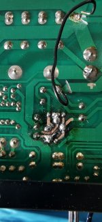
so here we go
i laid down an epoxy bed ontop and re drilled the holes for the new rectifier
i managed to re lay most of the old print, apart from one pice that was too far gone, but managed to connect the rectifier leg direct, and this gives it a bit of strength back.
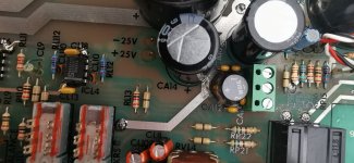
new filter caps uprated to 35v(not the main ones)
new ceramic caps uprated to 100v
new uprated rectifier uprated to 100v
new uprated caps and 10ohm resistor where it was burned
new connector block
looking into ways to fit the watchmen fuses but there isnt alot of room TBH
so now all i have to do is re attached the transfoermer and plug it into the lamp supply and see what happens as i cant realy see anything else that is obviously wrong
i laid down an epoxy bed ontop and re drilled the holes for the new rectifier
i managed to re lay most of the old print, apart from one pice that was too far gone, but managed to connect the rectifier leg direct, and this gives it a bit of strength back.
new filter caps uprated to 35v(not the main ones)
new ceramic caps uprated to 100v
new uprated rectifier uprated to 100v
new uprated caps and 10ohm resistor where it was burned
new connector block
looking into ways to fit the watchmen fuses but there isnt alot of room TBH
so now all i have to do is re attached the transfoermer and plug it into the lamp supply and see what happens as i cant realy see anything else that is obviously wrong
Attachments

Well that sounds promising at this point and that looks an excellent repair of the PCB.
I would check that the supplies (particularly the regulated rails) are all correct now, check the opamp outputs are at zero volts DC and check the main amps offset is zero.
If all seems OK then give it a listen. I know you will check the bias current 😉
I would check that the supplies (particularly the regulated rails) are all correct now, check the opamp outputs are at zero volts DC and check the main amps offset is zero.
If all seems OK then give it a listen. I know you will check the bias current 😉
- Home
- Amplifiers
- Solid State
- Creek 5050