How about "MOST currents take the path of lowest impedance"
But in fact current will take all available paths, inversely proportionally to each path's impedance.
Would help also; the most important point imo is that the impedance depends on the frequency region and as a result affecting loop area as well (and therefore affects EMI) .
Means that a solution working well above 10 Mhz might not work comparable below 500 Hz.
In some installations in some countries. In other places it will be different, sometimes very different.Speedskater said:The Safety Ground/Protective Earth wire runs back to the main breaker panel where it's connected to the Neutral.
Originally Posted by Speedskater
The Safety Ground/Protective Earth wire runs back to the main breaker panel where it's connected to the Neutral.
The SG/PE's main task is to trip the circuit breaker.
The Safety Ground/Protective Earth wire runs back to the main breaker panel where it's connected to the Neutral.
How would that work?In some installations in some countries. In other places it will be different, sometimes very different.
The SG/PE's main task is to trip the circuit breaker.
My understanding (which I am sure others will correct!) is that the UK mainly uses two different arrangements:
1. Each house has its own ground connection, derived from the external conductive sheath of the incoming mains cable. At the local substation, perhaps several streets away, the mains neutral is also grounded. This arrangement is usually seen in older houses.
2. A small group of houses share a common 'ground' connection, which is derived from the neutral on the mains cable in the street. The neutral is grounded at the local substation. This is seen in newer houses, and older houses which have been recently rewired.
The first arrangement has the advantage that the safety ground within the house is likely to be close in potential to the local ground potential. It has the disadvantage that the resistance seen by a fault current may be high so breakers may be slower to trip. Radio amateurs using an RF ground need take no special precautions.
The second arrangement has low impedance, but the 'ground' within the house may be rather different from the actual ground potential. This means that people cannot attach a local ground too, so anyone requiring an RF ground (or audio ground) must keep it carefully isolated from the safety ground.
Oh, I see, the lower case word 'ground' is causing us to co-mingle two different grounding systems.
1] Inside the building, Safety Ground/Protective Earth system, trips a circuit breaker in the event of a Ground Fault (short circuit). So if the Hot wire touches the case of our component, the circuit breaker will trip.
2] Outside the building, it's the connection to Planet Earth. In different locations, there are different systems for doing this. This system if for protection during thunderstorms, power company high-voltage failures and to keep your low voltage system (120/240V) near the same potential as your swimming pool.
I recently did an amplifier and there was slight hum audible was trying to debug but finally when i took the power ground and connected to the safety ground via 10ohm NTC the hum is gone but when i connected the same amp at other place where the voltage between Neutral and Safety earth is 1V Im getting the same hum again. So now its inevitable to correct the value which is appearing to the safety earth or the signal ground has to have some reference 0 value which is externally created. consder two trimmable regulators and balance the output to match zero voltage and connect the signal ground to that point.
why do you say so?
"The" reference point is "one" by definition.
You can NOT have two or more different points and call all of them "reference".
Please reread the title of this thread: Creating reference 0V ground
That means *one* in any Language
*where* ?
*how* will you measure it?
Please explain how if both test leads of a meter are touching the exact same point they might show a voltage , any voltage different to 0.
are you being deliberately obtuse? 😱
this has already been explained by DF96 in a post above.
Do you think that by repeating the same question you will get a different answer?
You are grabbing at straws.
Well intentiond people try to explain you how you are wrong and use different examples to get through your thick skull, explaining through analogy.
You are not interested at all in Truth, you just want to mess things up, for as long as you can.
Maybe there is some perverted satisfaction in that, dunno, I´m not a Psychiatrist, just a boring Engineer.
Won´t waste more time on a childish personality guy.
Maybe if everybody leaves this place and you are left alone, you way think of that as a "victory".
Ok, suit yourself, if that makes you happy.
I have nothing else to add since this is becoming circular, you have already been answered yet you want to keep the ball rolling by saying "no, I am not convinced" like a mantra so the same answers are given ove and over.
You have become a waste of time.
See?
To explain what happens at a reference point (single point by definition) you are introducing at least **TWO**
That´s what "common" means (to need to be called "common" you must be talking about 2 different points, no need to say so about a single/reference one)
That´s what "differential" means, you can only have a differential anything by talking about TWO different points, a reference "anything" can not be different to itself.
Let me expand the definition: you not only do not know anything about "voltage", now I see you don´t (or pretend not to) know about *any* parameter.
So my leaving this thread does not mean you "won" but simply than now you are treated as an incurable case.
I bet I´m not the only one doing or thinking so 🙄
when two points in same plane or the voltage difference on same point is zero i agree that but here is all about creating another virtual reference ground isolated from everything hope you got it.
Correct me if you disagree, but all house wiring is star, all the earth runs go back to your board's earth bar which is connected to the ground peg or a copper water pipe in days gone by.
Even a ground plane by definition is a star since current will run through least resistance probably the straightest line to the point of lowest potential. One should also keep in mind that only DC runs in the conductor all alternating currents move toward the surface of the conductor.
I would look at how return currents actually flow... The return path varies depending on frequency... A contiguous unbroken ground plane allows all returns to follow their desired path.
Skin effect is not going to have any effect for most of the frequencies and designs used on this site, so it doesn't really need to be considered at all.
Ground is a misnomer and the relevant thing really is having a point of reference. You can build all sorts of circuits that have no reference to ground what so ever. When you design your circuit you can decide yourself on what you want to use as reference.
Now, if you have different pieces of equipment that interact and they are designed with different point of references, there is the potential for problems.
It's common for the point of reference to be the "ground" in your outlet. If used in that way, there can theoretically be a difference in potential at the point of entry to your hifi equipment, but the reference is always that, a reference.
Improperly designed circuitry can have imbalances in their grounding scheme resulting in what is popularly referred to as ground loops.
If the safety ground has a potential then by definition the safety ground is not your potential reference, and so it can do little harm. Problems generally occur when different parts of the audio system use different reference points. People who don't understand voltage may misdiagnose this problem, and so try to apply the wrong solution. Sometimes the wrong solution might work by accident.rhythmsandy said:So now its inevitable to correct the value which is appearing to the safety earth or the signal ground has to have some reference 0 value which is externally created.
ok i got a denon 3300W receiver which has a preout and then used kyptonv2 as amplifier and found that there is some small groundloop issue low in amplitude but still audible from the surround speakers. I have used unbalanced interconnects.
Now when I checked the safety earth pin on the denon receiver i found that there is no third pin so there no scope of ground from there..
But i thought that removing the two 4148 with 10ohm resistor would solve the problem or i dont know why its used?
Once connected to the receiver im getting the ground loop issue but once connected to the PC with soundcard im not getting any hum.
What could be the problem here?
Attachments
Last edited:
This might not be the issue here but I'd start with using the same outlet/power strip. Then try shifting polarity of the plug.
Often you have one hot and one cold line in from the outlet and the cold one is used instead of the safety ground.
If the kyptonv2 amp is using the safety ground, that could be a possible issue?
Often you have one hot and one cold line in from the outlet and the cold one is used instead of the safety ground.
If the kyptonv2 amp is using the safety ground, that could be a possible issue?
I also think switching polarity in the Denon would/could solve the problem in this case. I was wondering why nobody mentioned a balanced power supply as this would be the simplest solution for creating a reference ground independent from the mains. Much cheaper than the Telos and most likely approved by all electronic engineers.
The Safety Ground/Protective Earth system needs to be extremely robust. It may be called on to deal a thousand amps until the breaker trips. Failure in the SG/PE system is not an option. An active method is not a safe choice.my call is all about how to make safety earth clean simple by an active method.
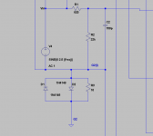
ok then lets leave the safety earth as is. Now what if a reference 0V is created using an active method like using two regulators with resistor dividers creating a trimmable voltage reference and use that for signal ground?
You can create any reference point you like as long as all the equipment use the same reference.
can that active reference point be only for signal ground?You can create any reference point you like as long as all the equipment use the same reference.
The voltage we're talking about is the difference in potential between the reference and the signal. Signal ground can be completely separated from safety ground.
Once you stick a transformer in there the designer can do as he likes.
Now, there are common conventions that are used because it makes things easier or cheaper but if you want to you could build a complete system that is floating and separated from safety ground.
Once you stick a transformer in there the designer can do as he likes.
Now, there are common conventions that are used because it makes things easier or cheaper but if you want to you could build a complete system that is floating and separated from safety ground.
The voltage we're talking about is the difference in potential between the reference and the signal. Signal ground can be completely separated from safety ground.
Once you stick a transformer in there the designer can do as he likes.
Now, there are common conventions that are used because it makes things easier or cheaper but if you want to you could build a complete system that is floating and separated from safety ground.
Thats very nice and kind input you have given will try creating a reference for the signal ground.
- Status
- Not open for further replies.
- Home
- Member Areas
- The Lounge
- Creating reference 0V ground