I am struggling to think of what sort of noise could consist of something which is not some combination of common-mode and differential mode-noise. Of course, in the case of common-mode noise you have to define your voltage reference but if this is the ground wire then by definition there cannot be any ground noise.rhythmsandy said:Mains EMI filters dont filter out the ground noise they filter the common mode and differential mode noises.
I suspect you still have not grasped the true nature of voltage. I will say it again: there is no such thing as a voltage.
why do you say so?Agreed on the relativity potential. Now the reality is when you connect two different equipments they will see different references
"The" reference point is "one" by definition.
You can NOT have two or more different points and call all of them "reference".
Please reread the title of this thread: Creating reference 0V ground
That means *one* in any Language
*where* ?and also you will have some emi induced
*how* will you measure it?
Please explain how if both test leads of a meter are touching the exact same point they might show a voltage , any voltage different to 0.
are you being deliberately obtuse? 😱
this has already been explained by DF96 in a post above.
Do you think that by repeating the same question you will get a different answer?
You are grabbing at straws.and yes as you said there will be ground noise so how do you eleminate it?
Well intentiond people try to explain you how you are wrong and use different examples to get through your thick skull, explaining through analogy.
You are not interested at all in Truth, you just want to mess things up, for as long as you can.
Maybe there is some perverted satisfaction in that, dunno, I´m not a Psychiatrist, just a boring Engineer.
Won´t waste more time on a childish personality guy.
Maybe if everybody leaves this place and you are left alone, you way think of that as a "victory".
Ok, suit yourself, if that makes you happy.
I have nothing else to add since this is becoming circular, you have already been answered yet you want to keep the ball rolling by saying "no, I am not convinced" like a mantra so the same answers are given ove and over.
You have become a waste of time.
See?Mains EMI filters dont filter out the ground noise they filter the common mode and differential mode noises.
To explain what happens at a reference point (single point by definition) you are introducing at least **TWO**
That´s what "common" means (to need to be called "common" you must be talking about 2 different points, no need to say so about a single/reference one)
That´s what "differential" means, you can only have a differential anything by talking about TWO different points, a reference "anything" can not be different to itself.
Let me expand the definition: you not only do not know anything about "voltage", now I see you don´t (or pretend not to) know about *any* parameter.
So my leaving this thread does not mean you "won" but simply than now you are treated as an incurable case.
I bet I´m not the only one doing or thinking so 🙄
Marce, have you ever seen spindly star grounds anywhere except in audio? Just wondering...
Myself, I'm going balanced, starting with a Modulus-86, which is waiting for enclosure drilling...
Myself, I'm going balanced, starting with a Modulus-86, which is waiting for enclosure drilling...
We use star grounds inside Emitter Coupled Logic integrated circuits. These are current mode devices whose noise margin is a couple hundred millivolts (but boy are they fast!). So it's crucial to minimize V = I*Z offsets. BTW the supply rails are -4.5V and GND. I will repeat that: minus 4.5V and ground. Why? Logic outputs are effectively the voltage across the collector load resistor of an NPN transistor. This means they are referred to the top supply. So let's call the top supply "Ground". Now logic outputs are voltages with respect to Ground. Trippy eh?
Marce, have you ever seen spindly star grounds anywhere except in audio? Just wondering...
Myself, I'm going balanced, starting with a Modulus-86, which is waiting for enclosure drilling...
In the past audio wasn´t the only system with quite low bandwidth requirements, so star ground (or quasi star ground) systems were commonly used.
As in reality there is no real single point possible (and often simply for practical reasons), all star ground systems are in fact more a series/parallel combination or using other words a star ground/bus ground combination.
Realizing that the designer should think about avoidance of common mode voltage coupling (means to carefully choose the currents that share a bus) and of course should try to control the loop areas.
The old golden rule "currents take the path of lowest impedance" does help but should be accompanied by the reminder that it is not a "digital rule" which means that curents are shared if different paths exists even if one has a higher impedance.
Last edited:
Marce, have you ever seen spindly star grounds anywhere except in audio? Just wondering...
Myself, I'm going balanced, starting with a Modulus-86, which is waiting for enclosure drilling...
No, even in't old days on double sided digital designs the Return and power was gridded to the the lowest impedance. Ever since I started layout analogue designs have usually been 4 layer with ground planes. Even when grounds are starred together (joined at one point) the grounds are separate planes. Its all about getting the lowest impedance connections for the return (0V's).
We use star grounds inside Emitter Coupled Logic integrated circuits. These are current mode devices whose noise margin is a couple hundred millivolts (but boy are they fast!). So it's crucial to minimize V = I*Z offsets. BTW the supply rails are -4.5V and GND. I will repeat that: minus 4.5V and ground. Why? Logic outputs are effectively the voltage across the collector load resistor of an NPN transistor. This means they are referred to the top supply. So let's call the top supply "Ground". Now logic outputs are voltages with respect to Ground. Trippy eh?
Logic outputs have always been a voltage referenced to ground, haven't they...
Anyone who wants to understand grounds... would benefit from reading the attachment above.
I believe ECL uses current, not voltage? This may or may not be relevant, as Ohm's Law will connect current and voltage.marce said:Logic outputs have always been a voltage referenced to ground, haven't they...
Mt statement cant be taken without the quote, it was a direct reply to the line...
Further with ECL like all high speed logic you need a plane for return currents to run on, doesn't matter whether its 0Vs or the gate supply, but a contigous plane for returns is critical.
So let's call the top supply "Ground". Now logic outputs are voltages with respect to Ground. Trippy eh?
Further with ECL like all high speed logic you need a plane for return currents to run on, doesn't matter whether its 0Vs or the gate supply, but a contigous plane for returns is critical.
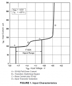
The ECL chips I designed, followed the F100K I/O standard displayed below; all logic signals were (negative) voltages with respect to ground. For those who may not remember, F100K was the 3rd generation ECL logic family. By that time, geometries had shrunk enough and the level of integration had risen enough, to finally let us use an actual bandgap voltage reference generator to achieve truly voltage- and temperature-compensated I/O. In previous generations of ECL, the gate switching threshold was set by two diodes, two resistors, and a fervent hope that the system designer watched his millivolts and his deltaTs very carefully.
And yes, inside the chip, we had star grounds. Several of them. We didn't have ground planes inside the chip. But we did have star grounds.
_
And yes, inside the chip, we had star grounds. Several of them. We didn't have ground planes inside the chip. But we did have star grounds.
Code:
F100K I/O specs:

-1810 mV < VIL < -1475 mV
-1165 mV < VIH < -880 mV
-1810 mV < VOL < -1620 mV
-1025 mV < VOH < -880 mVAttachments
Last edited:
Anyone who wants to understand grounds... would benefit from reading the attachment above.
Which is a good source and it illustrates afair the last point of my post i.e. "The old golden rule "currents take the path of lowest impedance" does help but should be accompanied by the reminder that it is not a "digital rule" which means that curents are shared if different paths exists even if one has a higher impedance"
Planes are fine but will not fix every potential problem or might even create some additional problems if the designer neglects the rule mentioned above (and in the last post).
The ECL chips I designed, followed the F100K I/O standard displayed below; all logic signals were (negative) voltages with respect to ground. For those who may not remember, F100K was the 3rd generation ECL logic family. By that time, geometries had shrunk enough and the level of integration had risen enough, to finally let us use an actual bandgap voltage reference generator to achieve truly voltage- and temperature-compensated I/O. In previous generations of ECL, the gate switching threshold was set by two diodes, two resistors, and a fervent hope that the system designer watched his millivolts and his deltaTs very carefully.
And yes, inside the chip, we had star grounds. Several of them. We didn't have ground planes inside the chip. But we did have star grounds.
_Code:F100K I/O specs: -1810 mV < VIL < -1475 mV -1165 mV < VIH < -880 mV -1810 mV < VOL < -1620 mV -1025 mV < VOH < -880 mV
When we used ECL or any fast logic on boards we always used planes.
Which is a good source and it illustrates afair the last point of my post i.e. "The old golden rule "currents take the path of lowest impedance" does help but should be accompanied by the reminder that it is not a "digital rule" which means that curents are shared if different paths exists even if one has a higher impedance"
Planes are fine but will not fix every potential problem or might even create some additional problems if the designer neglects the rule mentioned above (and in the last post).
On a board you have better control, between system components is where it usually goes wrong, the usual culprits are the low impedance (or more specifically low resistance) safety earth loop competing with the relatively high screen resistance of the interconnects, causing the lower frequency signals to take a different route and form a ground loop... We have discussed this many times, look for some of Jneutron's posts very informative.
On a board you have better control,.....
Sure, but you have to use it in a sensible way. Just throwing planes in might help if you are lucky, but in reality you´ll most probably end with a mixed star/bus/plane topology.
.....between system components is where it usually goes wrong, the usual culprits are the low impedance (or more specifically low resistance) safety earth loop competing with the relatively high screen resistance of the interconnects, causing the lower frequency signals to take a different route and form a ground loop... We have discussed this many times, look for some of Jneutron's posts very informative.
Which is imo a different topic.... (although of course related) 🙂
Marce, have you ever seen spindly star grounds anywhere except in audio? Just wondering...
Myself, I'm going balanced, starting with a Modulus-86, which is waiting for enclosure drilling...
Correct me if you disagree, but all house wiring is star, all the earth runs go back to your board's earth bar which is connected to the ground peg or a copper water pipe in days gone by.
Even a ground plane by definition is a star since current will run through least resistance probably the straightest line to the point of lowest potential. One should also keep in mind that only DC runs in the conductor all alternating currents move toward the surface of the conductor.
One way to summarize the link in #63 is: "at sufficiently high frequency you NEED a ground plane, because RiseTime<<Wiredelay". Another way to summarize it is "at sufficiently low frequency you DON'T NEED a ground plane, because RiseTime>>Wiredelay".
This is why ECL boards have groundplanes but the internal guts of ECL chips do not have groundplanes. Both of them run at the same clock frequency and have the same RiseTime, but the Wiredelays are two orders of magnitude apart.
This is why ECL boards have groundplanes but the internal guts of ECL chips do not have groundplanes. Both of them run at the same clock frequency and have the same RiseTime, but the Wiredelays are two orders of magnitude apart.
How about "MOST currents take the path of lowest impedance".......................................
The old golden rule "currents take the path of lowest impedance" does help but should be accompanied by the reminder that it is not a "digital rule" which means that curents are shared if different paths exists even if one has a higher impedance.
But in fact current will take all available paths, inversely proportionally to each path's impedance.
The Safety Ground/Protective Earth wire runs back to the main breaker panel where it's connected to the Neutral. The ground peg or a copper water pipe has nothing to do with it.Correct me if you disagree, but all house wiring is star, all the earth runs go back to your board's earth bar which is connected to the ground peg or a copper water pipe in days gone by.
For AC power and analog audio in the small conductors involved, skin-effect is not a factor.One should also keep in mind that only DC runs in the conductor all alternating currents move toward the surface of the conductor.
- Status
- Not open for further replies.
- Home
- Member Areas
- The Lounge
- Creating reference 0V ground