Andrew can you explain ground noise?Voltage is Volta with a ge added.
Then what is this so called as Ground noise?
This happens when you shake your box of ground, same kind of noise that a maraca makes. Ground boxes work the best if they are mechanically isolated/decoupled from the equipment stand, else it will cause ground noise.
Last edited:
Andrew can you explain ground noise?
First of all where does this term come from because ground has nothing to do with your signal reference and all I can think of is that some noise and unwanted signal is introduced into your reference. It has to be alternating else it will not be noise like.
If you are referring to "ground" as in earth or safety ground then yes there is a lot of rubbish conducted in the ground and if your system relies on this ground as its reference it is most likely that there will be a lot of noise.
Im talking about safety ground.First of all where does this term come from because ground has nothing to do with your signal reference and all I can think of is that some noise and unwanted signal is introduced into your reference. It has to be alternating else it will not be noise like.
If you are referring to "ground" as in earth or safety ground then yes there is a lot of rubbish conducted in the ground and if your system relies on this ground as its reference it is most likely that there will be a lot of noise.
If you might have seen the Douglas self 6e there is one topic regarding the wiring diagram for the proper grounding there you can see the safety earth is connected to the signal ground. Now dont you think that the noise is induced into the signal ground?
Attachments
There is no rule to tie your reference point of your amplifier to the safety ground. The safety ground is to protect you, not your signal. Ground noise exists, there are signals running around ground that you cannot imagine ranging from low frequency into RF. Think what a lighting strikes does, there is a potential difference between the strike point and any other areas.
Power generating plants use ground as a conductor, you will measure very little if any potential difference between the neutral and ground, thus there are noises generated by your neighbors washing machine, hair dryer, the guy down the road's ham radio and the like.
If you touch a bare input lead you hear a big buzz, this is due to the potential between you and ground.
I do not understand Douglas' drawing regarding safety ground.
Last edited:
There is no rule to tie your reference point of your amplifier to the safety ground. The safety ground is to protect you, not your signal. Ground noise exists, there are signals running around ground that you cannot imagine ranging from low frequency into RF. Think what a lighting strikes does, there is a potential difference between the strike point and any other areas.
Power generating plants use ground as a conductor, you will measure very little if any potential difference between the neutral and ground, thus there are noises generated by your neighbors washing machine, hair dryer, the guy down the road's ham radio and the like.
If you touch a bare input lead you hear a big buzz, this is due to the potential between you and ground.
I do not understand Douglas' drawing regarding safety ground.
Thanks now you got my point.
what self speaks is that to connect both safety earth and the reference ground. I have read that using that will reduce the ground loops. I was actually surprised by that in the beginning that how come safety ground is connected to the signal ground but if you see his drawings you will end up in the same doubt..
Ground Loops
I didn't say there is no such thing as voltage. I said there is no such thing as a voltage. Voltage is always, without exception, between two points. Simply understanding that means you can ignore much of what foolish people say about grounding.rhythmsandy said:Im surprised when you said there is no such thing as voltage?
You tell me. It is meaningless to say that the voltage reference has a voltage; by definition it must be zero. If you 'measure' something different then you are not measuring what you think you are measuring; in some cases you may be indirectly measuring AC magnetic fields.Then what is this so called as Ground noise?
I didn't say there is no such thing as voltage. I said there is no such thing as a voltage. Voltage is always, without exception, between two points. Simply understanding that means you can ignore much of what foolish people say about grounding.
You tell me. It is meaningless to say that the voltage reference has a voltage; by definition it must be zero. If you 'measure' something different then you are not measuring what you think you are measuring; in some cases you may be indirectly measuring AC magnetic fields.
Now take it in reality:
Any conductor has got resitance because of its natural ability to resist the flow of electrons and capacitance mostly because of stray capacitance and inductance either by length. Now having such properties will endup having some stray voltage even when its considered as 0V. Now that what i say there is nothing called as absolute zero or obvilion. When you say zero its very near to zero but not absolute zero.
what I said is to correct the variations in that reference what we generally take it as ground. If you can take a 6.5 digit multi meter and measure that reference point you will definitely get alternating voltage but very miniscule. Now you may ask me that will that really matter? If you use Raal ribbon tweeters you can clearly hear that difference so why cant one can correct it using some servo.
You-do-not-get-itNow take it in reality: ..... When you say zero its very near to zero but not absolute zero.
It IS absolute zero.
Not a thousandth of Volt, not a millionth of Volt but absolute zero/nought/nothing.
But let´s leave Electricity for a while, which often is not too intuitive, let´s get into something "mechanical" instead:
what is the length of a point?
please answer this.
here is the catch. Now when you say just a point the length is zero so hence the voltage difference is zero but what about the induced voltage into it through external electro magnet and RF fields?You-do-not-get-it
It IS absolute zero.
Not a thousandth of Volt, not a millionth of Volt but absolute zero/nought/nothing.
But let´s leave Electricity for a while, which often is not too intuitive, let´s get into something "mechanical" instead:
what is the length of a point?
please answer this.
what about the induced voltage into it
Voltage referenced to what?
I suspect you mean that current is induce in ground conductors, hence if the ground conductors have non-zero resistance then they will have a voltage across them, but now you need to decide where you are measuring the voltage, and what relevance that has has to your signals and their 0-volt reference.
All of which has nothing to do with whatever the device you mentioned is supposed to do.
I was speaking of reality: you know, that real place where the laws of physics are true rather than the imaginary place inside the head of many an audiophile where he can decide for himself how electrical objects behave.rhythmsandy said:Now take it in reality:
You do not understand voltage. Until you do, you cannot contribute to this discussion except by asking the sort of questions which onlookers, who also don't understand voltage, may ask.Any conductor has got resitance because of its natural ability to resist the flow of electrons and capacitance mostly because of stray capacitance and inductance either by length. Now having such properties will endup having some stray voltage even when its considered as 0V.
Irrelevant. We are not talking about an approach to some mythical 'zero' of voltage; voltage is quite unlike temperature. Temperature is defined at a point; voltage is not. By definition, the voltage of a point with respect to that same point is exactly zero - not approximately zero, or approaching zero, or nearly zero, or theoretically zero.Now that what i say there is nothing called as absolute zero or obvilion. When you say zero its very near to zero but not absolute zero.
No catch. A point has zero extent, and zero area. Therefore it has zero stray capacitance and zero loop area; therefore is has zero induction from local fields. To induce a voltage from an electric field you need a finite surface area. To induce a voltage from a magnetic field you need a finite loop area.rhythmsandy said:here is the catch. Now when you say just a point the length is zero so hence the voltage difference is zero but what about the induced voltage into it through external electro magnet and RF fields?
As soon as your 'point' becomes a line or an area you can have induction, but then you have many points so you have to speak of the potential difference between one point and another.
as per the Douglas self mentioned in his book to attach the safety earth to signal ground so then you will endup having noise in it. So in that case you need a correction or what Douglas self speaks is wrong?
Why?So in that case you need a correction or what Douglas self speaks is wrong
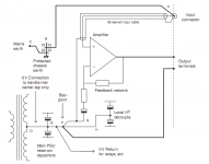
The amp/receiver measures the voltage difference across the input socket terminals.
Attaching a third wire from the isolated chassis to the return of the signal does not change that voltage difference.
BUT !!!!!
there is a Safety concern with the D.Self connection.
The Safety connection from Chassis to the amplifier may in the event of a serious and catastrophic mains circuit failure have to PASS Fault Current from the amplifier to the Protective Earth.
The connection MUST be capable of passing Fault Current approaching and even exceeding a kA and MUST survive long enough for the Mains fuse to rupture and the arc to extinguish.
Can the signal connection to the amplifier and the solder pads on the PCB pass that survivability requirement?
What is the "it" which has noise in?rhythmsandy said:as per the Douglas self mentioned in his book to attach the safety earth to signal ground so then you will endup having noise in it.
OK. Let's use a metaphor.
When you are in a moving elevator, or a moving car, your "ground reference" is moving, but you don't notice, because both your feet, or both sides of your bum sit on the same "ground reference".
The exact same thing happens for, say one printed circuit board with one ground plane which has no (or very little) current flowing through it. All its "GND" nodes are at the same potential. Therefore using it as a reference is OK.
If you look at a copper plane, the only way to have different potentials along its surface is to have currents going through it.
If you connect it to something at one point (like safety earth) then its potential will be that of safety earth, but all the electronics on it will feel just like you feel inside an elevator moving at constant acceleration. As long as everyone uses the same reference, there is no problem.
However, if you connect this "GND" to other bits of gear at TWO points, then a current will flow. Same if you shower it with electromagnetic waves. Then, the potential in your GND will no longer be equal everywhere. Two circuits using GND as reference, but taking it at two different points, will see different references. And you have ground noise.
OK. Let's use a metaphor.
However, if you connect this "GND" to other bits of gear at TWO points, then a current will flow. Same if you shower it with electromagnetic waves. Then, the potential in your GND will no longer be equal everywhere. Two circuits using GND as reference, but taking it at two different points, will see different references. And you have ground noise.
Agreed on the relativity potential. Now the reality is when you connect two different equipments they will see different references and also you will have some emi induced and yes as you said there will be ground noise so how do you eleminate it? Mains EMI filters dont filter out the ground noise they filter the common mode and differential mode noises.
> Now the reality is when you connect two different equipments they will see different references
If current flows in the wire which connects their grounds, which is always the case, then yes. You can minimize this by clever design, but never eliminate it.
> so how do you eleminate it?
By using balanced connections and balanced receivers with proper common mode rejection. Or transformers. Or optical.
Examples:
- All of pro audio (balanced)
- Ethernet (transformer coupled)
- SPDIF (transformer or optical)
- CAN, RS485, SATA, PCIe, USB, etc: differential (balanced) transmission
- Status
- Not open for further replies.
- Home
- Member Areas
- The Lounge
- Creating reference 0V ground