Hello there.
For a while now I've been doing some crazy experiments on different dipole configurations but this time I think I struck gold.
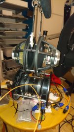
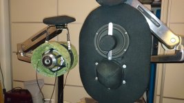
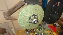
The setup is two opposed drivers mounted front to front. The rationale is that the distance between them is small enough that I can cross semi high, say 1500 hz ish but at the same time have perfectly symmetric front back dispersion.
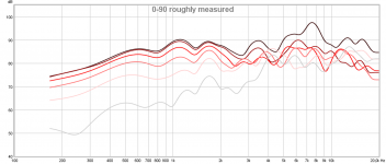
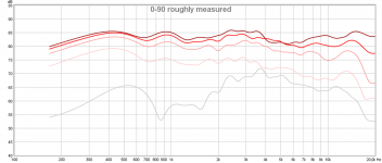
It does look crazy though, so I tought it would measure well enough up to 1 khz but above that show problems. In my measurements it performs nice enough up to 2 khz which is far far higher than I expected.
Last is the rough measurements after fooling around with some EQ and
adding the tweeter (Monacor DT-300 with WG-300 waveguide) crossed LR4 @ 1600 hz.
Lastly, all measurements are indoors at ~ 30 cm distance, far too cold for me to measure outdoors here in Sweden this time of the year
For a while now I've been doing some crazy experiments on different dipole configurations but this time I think I struck gold.
The setup is two opposed drivers mounted front to front. The rationale is that the distance between them is small enough that I can cross semi high, say 1500 hz ish but at the same time have perfectly symmetric front back dispersion.
It does look crazy though, so I tought it would measure well enough up to 1 khz but above that show problems. In my measurements it performs nice enough up to 2 khz which is far far higher than I expected.
Last is the rough measurements after fooling around with some EQ and
adding the tweeter (Monacor DT-300 with WG-300 waveguide) crossed LR4 @ 1600 hz.
Lastly, all measurements are indoors at ~ 30 cm distance, far too cold for me to measure outdoors here in Sweden this time of the year
Attachments

Last edited:
Are the drivers in-phase or out-of-phase?
Out of phase electrically.
What other dipole configurations have you tried?
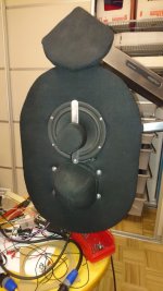
A normal top bottom configuration with DIY coaxial tweeters (Baffles are wool encased in linen):
Works pretty nice, great dipole radiation at 0-60 degrees. 60-90 between 2 khz and 6 khz is not a perfect dipole though so there is some bloom here. This was what I assumed was good enough with the drivers at hand which is why I was so suprised the front to front setup seems to work so well.
I've also tried a back to back configuration with a shallow midwoofer but the distance between the cones created a massive wide burp centered at 700 hz that no amount of stuffing could fix. It was not as compact as the other configurations either so I discarded it.
Next week I'll experiment more and see if I can raise the efficiency with some wool baffles like I can with a normal top down setup, and to verify that I get comparable low frequency response from either setup. If I have to sacrifice low frequency response then the setup isn't worth it as I'm already on thin ice by building a dipole.
Attachments

Last edited:
Out of phase electrically.
Then the gap is doing virtually nothing - may as well not have it.
I'd be interested to see what happens if they are in-phase. Then the gap would be critical and varying it would be quite interesting.
Then the gap is doing virtually nothing - may as well not have it.
I'd be interested to see what happens if they are in-phase. Then the gap would be critical and varying it would be quite interesting.
Yes, clamshell might be interesting. If they were in phase they wouldn't be a dipole
I can see what you're doing there, balancing front and back radiation. In reality you're never going to achieve a null at 90 degreesA normal top bottom configuration with DIY coaxial tweeters (Baffles are wool encased in linen):
Works pretty nice, great dipole radiation at 0-60 degrees. 60-90 between 2 khz and 6 khz is not a perfect dipole though so there is some bloom here.
Yes, clamshell might be interesting. If they were in phase they wouldn't be a dipole
It they are in phase then it would be a form of quadra-pole. Varying the gap width would tune the resonance frequency of the inner structure and make for some interesting results.
I like your experiment 🙂
You could try mounting one waveguide above the woofer and one below. That way you could bring the acoustic centers of woofer and the front firing waveguide (or rear firing, if you are behind the speaker) to equal distances from the listener.
One woofer would be sufficient, its rear output will probably be identical to the front output up to the crossover frequency.
Last edited:
More data!
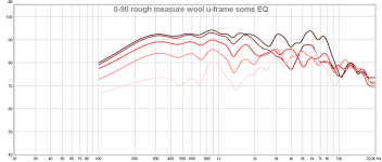
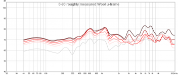
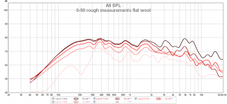
First up is wool U-frames to increase the low frequency output.
The first measurement is without EQ, the second with.
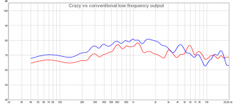
Next is comparing 0 degree response of the front to front u-frame to the top-down normal baffled dipole. I loose about 3 dB low in low frequency response but I gain a much more compact package. Pretty nice.
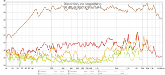
For science I also included distortion measurements @ 90 dB @ 1m and there I can verify that I can play as loud as I want to anyway. The amplifier is a F6 with a current feedback loop instead of voltage, ~ 600 ohm output impedance.
First up is wool U-frames to increase the low frequency output.
The first measurement is without EQ, the second with.
Next is comparing 0 degree response of the front to front u-frame to the top-down normal baffled dipole. I loose about 3 dB low in low frequency response but I gain a much more compact package. Pretty nice.
For science I also included distortion measurements @ 90 dB @ 1m and there I can verify that I can play as loud as I want to anyway. The amplifier is a F6 with a current feedback loop instead of voltage, ~ 600 ohm output impedance.
Attachments
-
 90 dB @ 1W, 120 hz LR4.png334.2 KB · Views: 126
 -
 Crazy vs conventional low frequency output.png109.7 KB · Views: 292
 -
 0-90 rough measure wool u-frame some EQ.png162.7 KB · Views: 274
 -
 0-90 roughly measured Wool u-frame.png183.6 KB · Views: 295
 -
 U-frame side.JPG115.7 KB · Views: 271
 -
 U-frame front.JPG127 KB · Views: 285
Last edited:
Next is a front baffle:
I only measured here with EQ, the same EQ as I used on the U-frame. I got about 1 dB more sensitivity on the low end but the side null isn't as nice as the u-frame and the setup is much larger so my current conclusion is to discard a flat baffle with a front to front setup.
From these experiments I'll probably go down the U-frame route if I continue along the front to front path.
Attachments

Last edited:
And now the extra measurements:
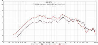
I compared the 0 degree low frequency output of a naked front to front setup compared to the conventional top bottom wool baffle, about 8 dB difference.
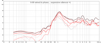
I also did a 0-90 where the drivers were wired in phase... an exotic way to generate silence in the bass region 😉
I compared the 0 degree low frequency output of a naked front to front setup compared to the conventional top bottom wool baffle, about 8 dB difference.
I also did a 0-90 where the drivers were wired in phase... an exotic way to generate silence in the bass region 😉
Attachments
Have you tried bolting them directly to each other, I don't think there's any need for the space between them if you're running them opposite phase. Or does the surround get in the way?
Hello there.
For a while now I've been doing some crazy experiments on different dipole configurations but this time I think I struck gold.
The setup is two opposed drivers mounted front to front. The rationale is that the distance between them is small enough that I can cross semi high, say 1500 hz ish but at the same time have perfectly symmetric front back dispersion.
It does look crazy though, so I tought it would measure well enough up to 1 khz but above that show problems. In my measurements it performs nice enough up to 2 khz which is far far higher than I expected.
Last is the rough measurements after fooling around with some EQ and
adding the tweeter (Monacor DT-300 with WG-300 waveguide) crossed LR4 @ 1600 hz.
Lastly, all measurements are indoors at ~ 30 cm distance, far too cold for me to measure outdoors here in Sweden this time of the year
That's an interesting setup, but I do not see any real advantages over a single woofer... at all. All this does is position the acoustic centers of the front and rear radiation farther apart, which just makes the dipole fall apart at a lower frequency. This is not an "advantage" AFAIK.
Also, the tweeter pair is too far apart to make a good dipole, as evidenced by all the crossing on and off axis responses above 2kHz. The lines should follow each other, tracking together, as much as possible. Instead it's a bit of a mess. If you measured with higher resolution you would see this more clearly. This is exactly what others have reported when trying to use two tweeters back-to-back as a dipole. Because of the magnet structure it is impossible to get the two acoustic centers close enough to create a dipole at high frequencies, where you want to use them.
But hanging the drivers by wire or string IS a good way to isolate the drivers from other drivers in the system. Good job there. I would not hang the tweeter from the woofers, however. All drivers need to hang separately. I use this approach in a "nude OB" system I built recently, and it works well. I used monofilament nylon (like very heavy duty fishing line) which is unobtrusive.
Last edited:
It's tempting to try and get perfectly symmetrical radiation front and back, but is there really much to be gained once you put it in a room?
So, let me see if I get this straight. The woofers are out of electrical phase therefore:
Between the woofers is a constant null. The space between the woofers creates a relatively small radiating (or non-radiating) aperture. Like a port, or slot whose energy is proportional to the opening described by a short cylinder.
Outside of this opening the woofers are essentially operating as dipoles. So examining the output on axis:
< ++++> ====< null >====<----->
So now we have a cardioid plus a built-in trap. Is that correct?
I have experimented with two woofers both open baffle one after another, in dipole and bipole arrangement, quite a while ago...I liked dipole better. You may find this interesting. Still use it today. Not my invention, others used it before. (Legacy audio for instance)
Audio Pages: Dipole subwoofers
Audio Pages: Dipole subwoofers
- Status
- Not open for further replies.
- Home
- Loudspeakers
- Multi-Way
- Crazy front to front mounted dipole that measures far better than I expected