Hi
Working on the Craigtone/Korneff 45 Amp.
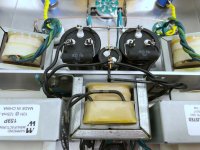
Harvested power/output transformers from a Sony TC500A reel to reel.
Have a question about secondary centre taps.
The filament on the 6SN7 is supplied by the Tamradio power transformer. I have a 5.0v transformer supplying the 5U4G and two 2.5v transformers supplying the 45’s.
I’m wondering what to do w the centre taps for the filament transformers?
The schematic does not show the centre taps on the 2.5v transformers connected to ground. And from what I understand, the centertap on the 5.0v transformer can be used for the b+ from the 5U4G?
Was hoping for some help in figuring out what to do about this?
Thanks!
Per


Working on the Craigtone/Korneff 45 Amp.
Harvested power/output transformers from a Sony TC500A reel to reel.
Have a question about secondary centre taps.
The filament on the 6SN7 is supplied by the Tamradio power transformer. I have a 5.0v transformer supplying the 5U4G and two 2.5v transformers supplying the 45’s.
I’m wondering what to do w the centre taps for the filament transformers?
The schematic does not show the centre taps on the 2.5v transformers connected to ground. And from what I understand, the centertap on the 5.0v transformer can be used for the b+ from the 5U4G?
Was hoping for some help in figuring out what to do about this?
Thanks!
Per

Thanks.
I’ve read about the potential for noise if using the 5U4G filament transformer center tap for the b+.
Any thoughts on that?
And if I don’t use it as the b+ supply, then what do I do with it?
P
I’ve read about the potential for noise if using the 5U4G filament transformer center tap for the b+.
Any thoughts on that?
And if I don’t use it as the b+ supply, then what do I do with it?
P
Thanks!
In the thread where Craigtone introduced this schematic, from what I gather, the centre taps on the 2.5’s were originally grounded in the drawing. Someone pointed out they shouldn’t be, and the ground connection was removed.
But then, I started reading, and was getting conflicting thoughts.
Does it make a difference where I leave them “hanging”? Or, is it better/worse if they are wrapped w the twisted pairs to the filaments and capped?
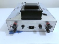
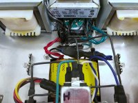
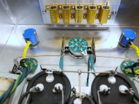
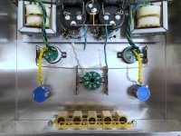
As you can tell from the photo, it’s a bit high density inside the chassis. Taking this apart to make changes will not be fun. It’s a bit of a 3D puzzle…
In the thread where Craigtone introduced this schematic, from what I gather, the centre taps on the 2.5’s were originally grounded in the drawing. Someone pointed out they shouldn’t be, and the ground connection was removed.
But then, I started reading, and was getting conflicting thoughts.
Does it make a difference where I leave them “hanging”? Or, is it better/worse if they are wrapped w the twisted pairs to the filaments and capped?
As you can tell from the photo, it’s a bit high density inside the chassis. Taking this apart to make changes will not be fun. It’s a bit of a 3D puzzle…
In a directly-heated tube, the filament IS the cathode. You must not ground the filament supply of a directly-heated tube unless you are using fixed-grid bias. This amp uses a cathode resistor to bias the tube so you have to leave the filament supply floating. As for the center tap, lop it off at the transformer and use some heatshrink tubing to cap it. I always leave an inch or so of wire in case I want to repurpose the transformer at some later time.
Thanks again!
Will do. And will tuck them away somewhere safely…
Last parts are arriving today, so will be able to finish up the build.
Now, I just need to find some 45’s for it 🙂
Will do. And will tuck them away somewhere safely…
Last parts are arriving today, so will be able to finish up the build.
Now, I just need to find some 45’s for it 🙂
Continuing a conversation from another thread…
The power supply is wired exactly as per the schematic. Using the 121v primary input to the transformer.
The power supply is wired exactly as per the schematic. Using the 121v primary input to the transformer.
All the transformers are running “hot”
Getting 3vac from the 45 transformers, and 6vac from the rectifier transformer.
Getting 3vac from the 45 transformers, and 6vac from the rectifier transformer.
I know. I was quite surprised to see those voltages. Granted, the transformers were not loaded when I measured it - other than the rectifier being in circuit to check DC.

Thanks!
I’m almost finished the final wiring. Will likely be ordering some 45’s this weekend.
Figure I might as well push on with everything as it is, and once I have it all assembled, will have a look at the voltages and address the discrepancies at that point.
Production is going to stop until next week Monday - family stuff - but will get back at it on Monday.
If you use Sony TC500A PT, the bottleneck of this transformer (and this schematic) is the limited current capacity of HT secondary.
Craigtone used 160mA one, you have only 110mA capable.
If you use shunt resistor across first capacitor of PSU, the transformer secondary current can cross 110mA limit (assuming 40mA DC current for each channel), and PT overheating quickly.
Instead of using shunt resistor to set output voltage of PSU, I suggest to use series resistor between rectifier and first capacitor.
Sample:

First of all, try to measure PT secondary DCR.
If it exceed recommended value for rectifier (at 300V/80mA) -5U4GB required only 20R- not necessary series resistor between primary and tube anode.
If you use 330V B+, be sure, that #45 dissipation (Uak*Ia) does not reach the limit (see datasheet).
Check it -for example- with such tool:
https://www.vtadiy.com/loadline-calculators/loadline-calculator/#calculator
Sample:

Craigtone used 160mA one, you have only 110mA capable.
If you use shunt resistor across first capacitor of PSU, the transformer secondary current can cross 110mA limit (assuming 40mA DC current for each channel), and PT overheating quickly.
Instead of using shunt resistor to set output voltage of PSU, I suggest to use series resistor between rectifier and first capacitor.
Sample:
First of all, try to measure PT secondary DCR.
If it exceed recommended value for rectifier (at 300V/80mA) -5U4GB required only 20R- not necessary series resistor between primary and tube anode.
If you use 330V B+, be sure, that #45 dissipation (Uak*Ia) does not reach the limit (see datasheet).
Check it -for example- with such tool:
https://www.vtadiy.com/loadline-calculators/loadline-calculator/#calculator
Sample:
- Home
- Amplifiers
- Tubes / Valves
- Craigtone/Korneff 45 Amp transformer center taps…