
Please don’t forget to ground the speaker negative, one shorted turn, and you end up with B+ on the speaker jacks, not good.
Thanks!
I will address the speaker ground! Where is the “best” place in the ground path to connect those?
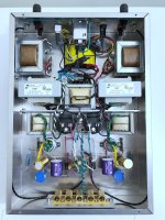
And all the resistors are there, just might not be easily visible 🙂
That two 600ohm taps are wrapped and capped, not visible as they are tucked away under the output transformers.
As they are 600ohm taps, a 600 ohm resistor? I wonder how they were handled in the TC500A at the headphone jack?
I will address the speaker ground! Where is the “best” place in the ground path to connect those?
And all the resistors are there, just might not be easily visible 🙂
That two 600ohm taps are wrapped and capped, not visible as they are tucked away under the output transformers.
As they are 600ohm taps, a 600 ohm resistor? I wonder how they were handled in the TC500A at the headphone jack?
Last edited:
Thanks.
I had obviously planned to just leave them twisted/capped. Had not considered doing anything w the 600ohm taps. But how these things work, is above my pay grade.
I had obviously planned to just leave them twisted/capped. Had not considered doing anything w the 600ohm taps. But how these things work, is above my pay grade.
I did not see any grid stoppers on the two 4 pin sockets, around 100 ohms would be a good value for the 45 tubes.
Rikaro is half right, you should not terminate the 600 on winding with a 600 ohm resistor. In the TC 500 a schematic it is terminated with a 3.3 k resistor at the line out jack. That’s exactly what I use in my build. A 3 W resistor.
If it was another four, or 8 ohm winding, you would not need to terminate it. But due to the fact that it is a 600 ohm winding, if it is not terminated, it will affect the high frequency response of the transformer. Don’t believe me? Measure it.
Technically, the best place to ground The speaker output would be where the cathode resistor for the output tube is grounded.
The 600 ohm winding on the transformer is in reality quite many turns of copper. 5K to 600 ohms is a 1:3 ratio. Output Transformers are complicated……. It can have parasitic effects on the frequency response if it’s just left, floating in the wind.
The 8 ohm winding is nowhere near as many turns of wire as the 600 winding…
Last edited:
I still don’t understand how “craigtone” Decided to use an input tube that is resistor loaded, with a gain of probably around 15, to drive an output to its biased at around -50 V…. You need a preamp has a heroic output to drive this amp…..
That’s why I went with a 6sl7 in my 45 amp, it has a gain of around 70, much better suited to produce a drive voltage for a DHT that requires so much voltage swing at its grid.
That’s why I went with a 6sl7 in my 45 amp, it has a gain of around 70, much better suited to produce a drive voltage for a DHT that requires so much voltage swing at its grid.
What difference did you measure?Don’t believe me? Measure it.
A dramatic reduction of high frequencies above 10k.
Minus 3db was around 13 kHz with open secondary, and around 18k when terminated.
It’s not like a normal speaker output secondary, it’s not a thick wire with a few windings, it is very thin wire, like the primary wire, there is a ton of it. As I stated above, 5K to 600 ohm is a 3:1 ratio.
Minus 3db was around 13 kHz with open secondary, and around 18k when terminated.
It’s not like a normal speaker output secondary, it’s not a thick wire with a few windings, it is very thin wire, like the primary wire, there is a ton of it. As I stated above, 5K to 600 ohm is a 3:1 ratio.
This is interesting. So, mctavish, let's say I am using a UTC LS-55 in a PP triode amplifier. The LS-55 has multiple secondaries for drive amp or PA service. Would I be better off to terminate the 500 ohm secondary? And if you know, how would this practice affect the use of global negative feedback?
I have no idea. I only have experience with these tiny single ended Sony outputs….
The problem with these is they are very small, and the 600 ohm winding takes up quite a bit of the coil. It definitely presents parasitic capacitance, and I hypothesize it is creating somewhat of a shield between the primary and eight ohm secondary. I really don’t know.
The problem with these is they are very small, and the 600 ohm winding takes up quite a bit of the coil. It definitely presents parasitic capacitance, and I hypothesize it is creating somewhat of a shield between the primary and eight ohm secondary. I really don’t know.
Then it should make a difference if one end of the winding is grounded.It definitely presents parasitic capacitance, and I hypothesize it is creating somewhat of a shield between the primary and eight ohm secondary.
Okay, thanks. Having tried both the UTC LS-55 and 57, I know that the LS-55's high-frequency behavior is more problematic because of the extra secondaries. I'll have to do a little research.
Thanks for all that info!
I will get some resistors and do an A/B comparison. Sadly, I have no tools to measure with…
Like I said, I built the unit exactly as per the schematic and when it’s all up and running, I will be sharing my findings for sure! Only other single ended tube amp I have is an EL84 that was built using the Heathkit SA-3 amp schematic.. I ended up with one I took apart and rebuilt with all new parts in a new chassis. I’m planning on stripping that build down and building the RH84 instead using the transformers from the SA-3. I’m contemplating getting another TC500A to harvest the iron and speakers from, and may use it to build the RH84.
From what I’ve read about this amp, it does indeed require a preamp. I have a few options on hand to try with it, and I’m working on a pre based on the RCA 12AU7 cathode follower. Just wanted to see what it sounds like.
Thanks again!
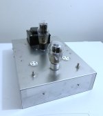
Tubes arrived! Bit delayed because of postal strike, but now they are here.
Amp is dead silent. No hum or hiss. Makes me very happy. Was also spared any magic blue smoke.
Problem, however, it’s distorting the sound like crazy!!!
Voltages are exactly where they should be - I think….
Any help would be greatly appreciated!
Thanks,
P
- Home
- Amplifiers
- Tubes / Valves
- Craigtone/Korneff 45 Amp transformer center taps…