Has anyone built this amp??
RH 807 - Tube Audio ...... RH DESIGN
is it as good as it looks on paper??
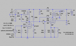
Also the value of the unmarked secondary ( the topmost one ) is 5v right?? Where can I get a traffo with these values?? I can't find one...
Second, any recommendations for the output transformers???
RH 807 - Tube Audio ...... RH DESIGN
is it as good as it looks on paper??
Also the value of the unmarked secondary ( the topmost one ) is 5v right?? Where can I get a traffo with these values?? I can't find one...
Second, any recommendations for the output transformers???
I've built a similar amp. See this thread. I used a 6LU8 TV sweep tube that contains a triode and a pentode. The amp is very cool.
For OPT's I use an Edcor XSE15-8-5k ($20/each). I have tried the CXSE25-8-5k ($70/each) as well. The latter is very good, but the former is a good place to start. The XSE15 is by far the best bang for the buck you'll find unless you find a high-quality OPT free somewhere.
And yes, I believe the unmarked winding feeding the filament on the GZ34 is a 5 V winding. You can do what I do and use a spare 6.3 V winding and a series resistor. I use a 5AR4 with a 0.68 ohm series resistor and measure 5.0 V across the filament. I recommend the Antek power transformers. Excellent bang/buck ratio.
~Tom
It will work much better with pentode, since parallel feedback by voltage overloads triode causing higher non-linearity.
I've built a similar amp. See this thread. I used a 6LU8 TV sweep tube that contains a triode and a pentode. The amp is very cool.
For OPT's I use an Edcor XSE15-8-5k ($20/each). I have tried the CXSE25-8-5k ($70/each) as well. The latter is very good, but the former is a good place to start. The XSE15 is by far the best bang for the buck you'll find unless you find a high-quality OPT free somewhere.
And yes, I believe the unmarked winding feeding the filament on the GZ34 is a 5 V winding. You can do what I do and use a spare 6.3 V winding and a series resistor. I use a 5AR4 with a 0.68 ohm series resistor and measure 5.0 V across the filament. I recommend the Antek power transformers. Excellent bang/buck ratio.
~Tom
Which antek power transformer did you use? I'm having a heck of a time finding one 325-0-325. Would this one work? Seems it would, i just need a separate 5v right?
This tube stuff is new to me...
That should be close enough since AnTec claims you can go 20% over without problems. You will have to use a dropping resistor (actually best to use two, one in each leg to keep the B+ Balanced) to get down from 6.3 to 5V for the filament of the rectifier tube. ( (6.3-5)/1.9 = 0.68 Ohm, use two .33 ohm two watt resistors.
You can tweek the cap and inductor values to adjust the B+ output, but it is probably fine as is.
The 807 is fine up to 750V, but you may have to adjust the screen resistor to keep it at 300V per the data sheet.
From a power standpoint the 4T360 is probably a better choice. Again the B+ won't be exactly 350, and you will have to tweek the screen resistor up to hold the voltage down. Higher B+ will still be well within spec for the tube, but plate dissipation is getting close to max (25W).
Last edited:
Thanks Gimp,
I'm still short a secondary though, the design calls for two 6.3v and one 5v. Is it important to keep the rectifier filament supply coming from a secondary on the same traffo? Or could I use the two 6.3v secs to heat the 8087's and ecc81 and a separate 5v transformer for the rectifier tube?
I'm still short a secondary though, the design calls for two 6.3v and one 5v. Is it important to keep the rectifier filament supply coming from a secondary on the same traffo? Or could I use the two 6.3v secs to heat the 8087's and ecc81 and a separate 5v transformer for the rectifier tube?
807 Filament current 0.9A * 2 = 1.8A
ECC81 Filament current (parallel at 6.3V) 0.3A
Total filament requirement 2.1A
No problem running all three tubes off the other 6.3V supply.
They keep the input tube on a different filament supply to help isolate from noise. This is nice to do, but not totally necessary.
During your construction, run seperate sets for twisted wires from the transformer to each tube filament to minimize interaction and hum pick up.
As Wavebourn said a triode(ECC81) is unsuitable as driver in a Schade-configuration. Before distortion-cancellation it will have ca 10% distortion.
So forget the ECC81 and go for something like a 6AU6 or even better an EF280 or D3a. An run them at high current!
You can also check out Pete Milletts PP and build it as SE.
So forget the ECC81 and go for something like a 6AU6 or even better an EF280 or D3a. An run them at high current!
You can also check out Pete Milletts PP and build it as SE.
A pentode driver, as Wavebourn and Revintage have suggested, is the more conventionally recommended driver for Schaded outputs. The Schading feedback has the effect of lowering the impedance greatly at the driver's plate. {Rfdbk/(output gain) paralleled with the driver load resistor} And the pentode has a high Z current source like output that drives that nicely without disturbing the pentode's internal characteristic.
But one should also keep in mind that the pentode has its own distortion problems to start with (the pentode internal transfer function operates the same as a triode with its plate stuck at some voltage, ie the screen V ). This is fixable by a high cathode degen. resistor (relative to 1/gm of the driver). (Similarly, the same fix works for a triode driver)
High driver current (boosting the gm) and a high driver tube gm spec, as Lars has suggested for the pentode, also work similarly well for the triode driver setup too.
The RH series seems to be designed so as to use highish driver distortion to cancel 2nd H dist. of the output tube. I would expect this to leave some noticeable 3rd and higher odd harmonic dists. But depends on the driver tube characteristics as to what finally gens up.
The 12AT7 has a nearly square law characteristic (like a Mosfet, so this will be largely 2nd harmonic dist.) as can be seen by its almost linear ramp of gm versus current (and badly skewed Mu curves):
http://scottbecker.net/tube/sheets/093/1/12AT7.pdf (page 4)
It is interesting to compare the 12AT7 with the nearly identically spec'd normal triode in the 6LU8:
http://scottbecker.net/tube/sheets/123/6/6LU8.pdf (page 4)
Which has the usual curved gm curve and nearly flat Mu curves.
An even more extreme case (beyond 12AT7) is the triode in the 6LQ8/6KR8:
http://scottbecker.net/tube/sheets/135/6/6KR8A.pdf (page 7)
Which might be interesting to try for a triode driver as well. And if that doesn't sound good, it's got a high gm pentode next door sitting ready. (switchable?)
Since no one seems to have ever published the measured FFT spectra for any RH type amplifiers, the relative success of this harmonic cancelllation strategy is still a mystery. Other attempts to do so have not often been well received, but maybe they didn't use the right driver characteristic. (I would expect a conventional triode, like in the 6LU8, to produce noticeable odd harmonic additions in this Schade setup.)
Don
Hi Don;
I've found the best tube for such driver is 6Z52P (or 6J52P - hard to match Cyrillic to Latin letters - 6Ж52П).
In my Pyramid-VII and Pyramid-8 amps (P-P configuration) I use couple of 6P15P tubes, with a long tail.
I've found the best tube for such driver is 6Z52P (or 6J52P - hard to match Cyrillic to Latin letters - 6Ж52П).
In my Pyramid-VII and Pyramid-8 amps (P-P configuration) I use couple of 6P15P tubes, with a long tail.
This is a theoretical model of a pentode/pentode Schade using the pentode-section of the dirt-cheap 6F12P.
About distortion cancellation my theory is that it works best with two-stage triode/triode or pentode/pentode amps. This because driver and output-tube then have more alike characteristics (that cancels due to the fact that they are of opposite phase).
About high current it has shown that many pentodes have their most linear area there. Also as we go from voltage to current drive it shouldn´t be a drawback to add a little juice😉.
If one also check Pete M´s site there are more than one design that relies on driver-pentodes.
Wavebourn,
Do you know any russian 807-style topcap pentodes, now that the 807 is hyped?
Attachments
Last edited:
Hi Lars;
pentode section of 6F12P is equal to 6J53P (smaller sister of 6J52P)
Also, here is my driver (drives GU-50 tubes with parallel feedbacks):
http://wavebourn.com/forum/download.php?id=119&f=7
pentode section of 6F12P is equal to 6J53P (smaller sister of 6J52P)
Also, here is my driver (drives GU-50 tubes with parallel feedbacks):
http://wavebourn.com/forum/download.php?id=119&f=7
Last edited:
pentode section of 6F12P is equal to 6J53P (smaller sister of 6J52P)
Hi,
Got that tip from you before, but didn´t find them at eBay at that time. But I have good stash of the 6F12P😎.
Will look into you GU-50.
Will look into you GU-50.
They are cheaper than 807, but much better! They can take more than 100W of abuse, and stay alive: Telefunken designed them for military transmitters, so anodes were made from nickel alloy.
I presented a pair of them to SY couple of years ago; I don't know if he ever tried them, or put on a demo stand as a gift from a friend. 😎
So what I'm seeing here is that as designed this amp may not be ideal. But for my first build it's okay though right? Seems I can endlessly tweak it using different voltage and tubes.
So what I'm seeing here is that as designed this amp may not be ideal. But for my first build it's okay though right? Seems I can endlessly tweak it using different voltage and tubes.
No ideal amps exist. All of them are optimal, depending on criteria.
Wavebourn,
Do you know any russian 807-style topcap pentodes, now that the 807 is hyped?
G-807 is a copy of 807; 6P7S is the same with octal socket.
Just in passing ... I did not notice comment on the large unbypassed 10K screen resistor in the original schematic. Apart from interfering with pentode characteristics, such a large resistor will also adversely affect operation especially with beam tubes with their quite substancial variation in current drawn depending on the output?
So what I'm seeing here is that as designed this amp may not be ideal.
If you mean the amp from your first post, it is designed from slightly wrong assumptions it is even worse than "not ideal"😉. Already in RDH 1954(?) they recommended to avoid triode-drivers so why use them now?
Last edited:
"So what I'm seeing here is that as designed this amp may not be ideal."
Well, in all fairness, the RH... amplifiers do seem to be very well liked by those who have built them. I would just leave a little room with the chassis to experiment further, and provide a little reserve capability in the power xfmr to accomodate alternative tubes (triode or pentode) that might be interesting. The circuit is simple, so easy to mod.
The question in my mind is whether the rather non-linear 12AT7 (it is a mixer tube after all) is succesfully managing to distortion cancel the output stage without adding much odd harmonics, or whether these people just like the sound of the distortion they are getting. With no measurement FFT ever presented, who knows?
The 12AT7 is also well liked in many differential stages, where the 2nd harmonics would cancel, indicating low higher odd harmonics possibly. Notice that in the differential case, the complementarily ramping, nearly straight, gm curves for the 12AT7 sum to a near constant flat gm overall (in class A P-P of course). If, instead, one uses the usual "best" constant Mu triodes in a differential stage, their curved gm curves sum (complementary wise) to a curved gm hill in the center. This is responsible for the usual odd harmonics eminating from differential stages with large signals.
So 12AT7 and similar "bad MU curve" tubes (usually with highish gm) do have there place. These type of tubes generally seem to have a round cathode, a grid that is crimped down so as to be nearly shrink rapped around the cathode, and a flat plate. This puts the grid wires in mis-alignment with the equipotential lines between the cathode and plate, causing the varying Mu curves. The high gm achieved this way may be responsible for the ramping gm curve by means of heavy grid wire "island effect".
Don
Last edited:
- Status
- Not open for further replies.
- Home
- Amplifiers
- Tubes / Valves
- Couple idiot questions....