Just in passing ... I did not notice comment on the large unbypassed 10K screen resistor in the original schematic. Apart from interfering with pentode characteristics, such a large resistor will also adversely affect operation especially with beam tubes with their quite substancial variation in current drawn depending on the output?
That's interesting. One of my PP amps uses 6P1P outputs with screens of each in the pair joined and connected to 260v B+ via 1k5 with no bypassing. Would bypassing be preferable, or maybe a voltage reg like the LR8.
I'm trying to understand the sonic implications of varying screen current in a beam tetrode. Also, what are the implications of the screen at a higher potential than the plate? Good or bad?
Newbie stuff sorry.
Gary
"I did not notice comment on the large unbypassed 10K screen resistor in the original schematic."
Well, a high screen resistor would certainly soften clipping in one direction as the screen current suddenly rises with saturated (minimum) plate voltage. (By dropping the screen voltage.) But 10K seems very high, so maybe some dynamic gain compensation is intended in the output pentode's "linear" region.
(ie, countering some of the non-linear 3/2 power law characteristic of the pentode) Seems the design was tweeked by ear until they got the sound they liked best.
"One of my PP amps uses 6P1P outputs with screens of each in the pair joined and connected to 260v B+ via 1k5 with no bypassing."
This would seem to be intended to soften clipping in both P-P directions by dropping the screen voltage when a plate V drops into the saturation region (via suddenly increased screen current). Having the two screens connected together would tend to cancel out any variation of the screen voltages while the two tubes are in the linear P-P region. Well, providing they are operating in class A. For class AB or B, I would think that a bypass cap there would be a good idea.
"what are the implications of the screen at a higher potential than the plate? Good or bad?"
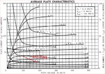
Well, the screen current takes off when the plate voltage gets down to the 50 to 100V range. The resistor in the screens will protect them from over heating by dropping the screen voltage. So the screen resistor is a useful safety factor.
Don
Well, a high screen resistor would certainly soften clipping in one direction as the screen current suddenly rises with saturated (minimum) plate voltage. (By dropping the screen voltage.) But 10K seems very high, so maybe some dynamic gain compensation is intended in the output pentode's "linear" region.
(ie, countering some of the non-linear 3/2 power law characteristic of the pentode) Seems the design was tweeked by ear until they got the sound they liked best.
"One of my PP amps uses 6P1P outputs with screens of each in the pair joined and connected to 260v B+ via 1k5 with no bypassing."
This would seem to be intended to soften clipping in both P-P directions by dropping the screen voltage when a plate V drops into the saturation region (via suddenly increased screen current). Having the two screens connected together would tend to cancel out any variation of the screen voltages while the two tubes are in the linear P-P region. Well, providing they are operating in class A. For class AB or B, I would think that a bypass cap there would be a good idea.
"what are the implications of the screen at a higher potential than the plate? Good or bad?"
Well, the screen current takes off when the plate voltage gets down to the 50 to 100V range. The resistor in the screens will protect them from over heating by dropping the screen voltage. So the screen resistor is a useful safety factor.
Don
Last edited:
Since no one seems to have ever published the measured FFT spectra for any RH type amplifiers, the relative success of this harmonic cancelllation strategy is still a mystery.
Don
Don
The RHxx designs are based on an old feedback method that commercially has been largely overlooked.
Basically you get feedback from the plate to the plate of the previous tube through a resistor which means there is no phase lag in the feedback which is extreemly important.
Manufacturers were more concerned in showing the customers max output, minimum distortion and a flat frequency response. This max output at minimum price was achieved by using push pull, the THD has no relation to the fact that second (even) order distortion is hardly noticeable but odd distorion is very annoying. Also the distortion has to be in a waterfall effect (2nd > 3rd > 4th > 5th etc).
Most manufacturers take the feedback loop from the secondary side of the transformer so they have a nice looking flat frequency response. However the transformer introduces magnetic lag which leads to phase shift which is different at different frequencies and what is rather annoying. Taking the feedback of the secondary allowed the manufacturers to use real cheap output transformers.
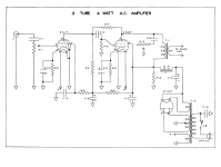
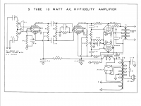
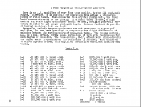
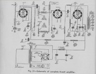
What Alex showed was something that was already well known in the 1940's. Look at the two designs that I will upload from the book of "practical amplifier diagrams" which was published in 1947. Today with better output transformers (preferbly those that have been wound interleaved) we do not need to concern us too much with the 2nd harmonic generated in the OPT. Neither should we be worried about the frequency range so we can take the "short feedback loop" or "inverse feedback" as mentioned in the RCA manual # 20, 26, 30 amongst others or the Radiotron Handbook 3 and get a very nice sounding amp. Ever wondered why so many have build this amp and then proceeded to buying more expensive output transformer to build an even more "visually appealing" and "technically advanced" version of the same amp? If that is not an endorsement of an design then I do not know what is.
Some have wondered about using the RH in PP so I am attaching abalanced PP design using this kind of feedback too. In both designs there is some form of tone control incorporated which imho should be left away (the pot and capacitor in series across the primary of the OPT).
At this moment I am personally sourcing the parts for a RH but have not decided yet if it will be the RH807 but with the 6L6-GC or the RH88.
Peace and happy listening.
AM
Attachments
Last edited:
..... But 10K seems very high, so maybe some dynamic gain compensation is intended in the output pentode's "linear" region.
...
Not that uncommon, I was wondering about this myself until I found a schematics in the "Amplifiers Builder's Guide" publication number 33 by the editors of Radiocraft. (Especially after I read some STC documentation over the 807).
See attached scan where a 5000 resistor is used (although this has a capacitor added but I read somewhere that Alex Kitic experimented with that and a stabilised voltage too but found this to be the best solution)
Peace and happy listening
AM
Attachments
Power supply considerations
The only issues I have with a lot of the "modern" designs of power supplies is that it does not ake into consideration the life expectancy of the tubes.
Please see the document "Techniques to maximize power tube life" by David C Gillispie ( which is freely downloadable from audioxpress).
AM.
The only issues I have with a lot of the "modern" designs of power supplies is that it does not ake into consideration the life expectancy of the tubes.
Please see the document "Techniques to maximize power tube life" by David C Gillispie ( which is freely downloadable from audioxpress).
AM.
Attachments
Basically you get feedback from the plate to the plate of the previous tube through a resistor which means there is no phase lag in the feedback which is extreemly important.
Actually, from plate to grid.
Since it is from plate, it is a feedback by voltage that lowers output resistance (feedback by voltage).
Since it is to the grid, it lowers input resistance (parallel feedback). Equation for amplification factor roughly includes resistance of feedback resistor and resistance of the previous stage that depends on Ri of the tube that drives an output stage. SinceRi is non-linear, an overall transfer function of 2 stages will be non-linear, even though a feedback linearizes an output stage.
That's why linearity of output resistance of the driver stage is so critical.
What Don were speaking about, he analyzed possible cancellation of non-linearities of both stages, that is quite a bit more complicated than ancient articles discuss.
I personally don't expect such cancellation, that's why prefer to use long tailed pentodes to drive output stages with parallel feedback by voltage.
Interesting examples showing 2 triode drivers and one pentode driver. Also see Gary Pimm's Tabor amps and Pete Millett's "Engineer's Amp", both using the proper pentode drivers with direct plate-grid feedback in push-pull topology.
First description I'm aware of is 1938, in "Beam Power Tubes" by O.H. Schade where he shows that tetrodes with plate-grid feedback behave in-circuit like low impedance triodes, including a push-pull amplifier circuit example. He shows series (voltage) feedback summed with an interstage transformer but the principles are the same.
With parallel (shunt, current...) feedback I think it comes down to 2 things.
1. The internal anode resistance of the driver is in parallel with the "equivalent load resistance" (which is the parallel feedback voltage current swing / driver current swing). This creates a partial feedback shunt, decreasing the amount of feedback (not necessarily a bad thing).
2. The triode is loaded with an equivalent load resistance below it's own internal resistance, resulting in potentially asymmetric current swings and a lot of even harmonic distortion. The situation is not unlike the bottom triode of a cascode, for which there are some operating regions of some triodes that yield acceptable results.
Personally, I prefer the pentode driver with high ratio of internal resistance to equivalent load in this circuit. This makes it a better voltage/current converter and results in lower impedance at the output for any given gm power tube. But the pentode operating range should also be chosen for optimum linearity and distortion profile. There is a big difference:
High Gm driver pentodes
Pentodes can work down into 5K loads, which is a good place in the operating region to be so as to reduce the effects of wiring capacitance, Choke windings, etc. on the feedback response.
PS an unbypassed cathode resistor on the driver tube reduces the gm (sets input sensitivity), increases plate resistance (better V/I converter), and will linearize the driver for smaller signal swings (less gm variation). Works for pentode and triode drivers.
Cheers,
Michael
Attachments
Last edited:
I agree completely with the pentode being the bog standard driver approach here (Schaded feedback, or plate to grid fdbk) as advocated by Lars, Wavebourn, Michael, .... It keeps the feedback network near linear with its high plate Z. Then some cathode degeneration gets added to linearize the pentode.
Using a triode driver is of interest if one wants to "tilt the feedback table" a bit to counter a known error tendency in the output stage. Since a pentode output tends to conduct more aggressively at high current (3/2 power law, or more like 2 power law for most power tubes, causing gm increase at high current), a little variation in the triode driver output impedance has the right phasing to counter the 2nd Harmonic distortion of the output stage. So one can degenerate the triode driver cathode until one gets the right amount of Rp variation wanted to null 2nd H. (Hopefully the driver still has some gain left after that, so a high gm triode is called for)
This only works for 2nd harmonic though, because the driver and output stages are not tracking V or I wise. Since a heavily loaded triode tends to increase all orders of harmonic distortion, (not just 2nd) one wants a tube that is close to square law (2 power) that mainly produces 2nd harmonic dist. (additional 3rd harmonic being the principle effect from the usual curved gm characteristics of constant Mu tubes) Which brings one to "bad Mu curve" tubes like 12AT7 or similar (triodes in 6LQ8, 6KR8, 6AU8, 6BH8,.... and many others) which have a near linear ramp of gm versus current at a fixed plate voltage. (like a Mosfet)
Alternatively, one could try a pentode with a lowish Rp to get the same dist. cancellation effect, and tweek the cathode resistor around to null 2nd H. (the pentode in a 38/12HE7 comes to mind for low Rp at 6200 Ohm, the 38V filament version allows one to power up just the pentode filament with 21V across pins 10 and 12, but 10W plate diss. is a bit of overkill here. A darn cheap tube though, $0.35 on sale lately. someone once threatened to carpet bomb 38HE7s on anyone who came up with a use for them)
Don
Last edited:
Well, the screen current takes off when the plate voltage gets down to the 50 to 100V range. The resistor in the screens will protect them from over heating by dropping the screen voltage. So the screen resistor is a useful safety factor.
Unless I misunderstand, you are talking of signal conditions; the plate going down during negative signal swings. But if a screen voltage drops under those conditions, it will promote 2nd harmonic distortion! (...unless the screen voltage is 'force-dropped' as in UL, and not going up/down according to its own current.) I am always a little apprehensive of a screen 'doing its own thing' (referring more now to voltage amplifiers) - I have seen graphs of distortion variations of 4:1 by just varying the (dc) screen voltage with all else being equal - and this is oscillatory, meaning going through several good/bad distortion areas as the G2 voltage goes from low to high. There is thus not necessarily one optimum, there are several, and they can shift about according to other parameters (wish I had never seen that EF86 analysis!).
Regarding fears of plate-swinging-below-screen-voltage during signal swings, one must again keep in mind the average effect - every alternate cycle the plate will go 'far' above Vg2, averaging the heat generated. When tube specs say that plate and screen can work at the same voltage, this is taken into account by the designer. E.g. provided average dissipation is within spec, a (say) KT88 with Va = Vg2 = 500V max. will be happy even though Va = 80V and Vg2 remains at 500V steady every other half-cycle, because during the alternate half-cycles Va will = 920V with Vg2 only at 500V. This is how I take the specs (and supported by the manufacturer). Thus one also finds that where max Vg2 is given as lower than max Va, for e.g. UL the max Vg2 is increased to = Va. (Vg2 is thus allowed to go above 'safe spec', but only while Va is much higher.)
So what I'm seeing here is that as designed this amp may not be ideal. But for my first build it's okay though right? Seems I can endlessly tweak it using different voltage and tubes.
For your first built it will probably be more than just OK - if you have decent iron.
One concern with the RH807 could be the sensitivity, depending on your source or preamp. It will require about 1.4V RMS input for full power.
The EL84 variant is easier to drive, and the dangerous high voltages are a little less dangerous.
If you build the chassis with space for two separate input tubes, you will have near endless alternatives for tweaking and modifications with both input/driver tubes and combination of feedback schemes.
SveinB.
I've been following this conversation as best I can with the help of my RCA manual pdf and google. I'm sold that there are other (pentode) designs that would be more fruitful, and the low gain issue is a bit of a concern for me...
I'm considering the Abdellah PP, does anyone have any other suggestions for a first (non-pcb) tube amp? I'd be better off with a highish gain in the amp so that I can still use my passive linestage, and 4+ watts are needed to drive my present speakers adequately.
The discourse has been very informative, don't stop on my account. But any and all suggestions welcome!
P.S. I'm partial to a tube-rectified design...
If you build the chassis with space for two separate input tubes, you will have near endless alternatives for tweaking and modifications with both input/driver tubes and combination of feedback schemes.
SveinB.
Better still is to use two tubes and only use one half of the tube wired / heated. Makes sure that they have the opposite sides wired in.
This allows you to do an A-B comparison between different driver tubes but more importantly something else: not every driver has exactly the same gain on both triodes, it is easier to match if you have different tubes. And if one side goes bust then you can swap them around and use the other side.
Like Svein mentioned - you can also experiment with other tubes like pentodes should you fancy that.
happy listening
AM
another KT88 SE design
You may want to look at this as well: Simple 7 Watt pr/ch Ultra linear SE "office amp" with shunt feedback
AM
You may want to look at this as well: Simple 7 Watt pr/ch Ultra linear SE "office amp" with shunt feedback
AM
Hi
Another newbies drawn to the RH 807.
I think it must be related to the positive feedback from all builders.
quote:
[special=Well, in all fairness, the RH... amplifiers do seem to be very well liked by those who have built them. Don]%[/special]
This will be my second tube amp.
The first amp was a Morrison Micro 3.5W.
Initially build to print then converted to a various other 2A3 designs,
JE Labs Simple 2A3
JE Labs 2001 Edition 2A3
Time Bandit
Then back to the Morrison, which sounds pretty good
At the moment I am proposing to build the amp as proposed by Alex, adding a potentiometer before the input tube.
I will also add two separate (ECC81) input tubes as suggested by [special=SveinB]%[/special] to allow [special=‘near endless alternatives for tweaking and modifications’.]%[/special]
Although at this stage I have no idea how to design/incorporate a new front end into the amp.
I have the 807’s in hand and the transformers on order; this was done before I came across this thread.
Before proceeding further I think I should ask for some advice,
The triode/pentode input has been mentioned on other threads but it appears to be limited to a discussion, has anyone built and compared the RH 807 in both configurations?
Quote:
[special=One concern with the RH807 could be the sensitivity, depending on your source or preamp. It will require about 1.4V RMS input for full power. SveinB]%[/special]
I will be connecting a CD player directly to the input, I don’t have the actual data for my player but as I understand it the industrial standard is 2V RMS, will this cause a problem?
And a question on the two separate input tubes,
Quote:
[special=Better still is to use two tubes and only use one half of the tube wired / heated. Makes sure that they have the opposite sides wired in. AM]%[/special]
If you are only using half of the tube how and why is the other half ‘wired in’?
Regards
John
The other half of the tube isn't wired in.
He means that you wire the opposite pin numbers. So that the left half of one tube is active, and the right half of the other tube.
Analogy: If the tubes were monkeys; put the signal through the right arm and right leg of one, and the left arm and left leg of the other.
He means that you wire the opposite pin numbers. So that the left half of one tube is active, and the right half of the other tube.
Analogy: If the tubes were monkeys; put the signal through the right arm and right leg of one, and the left arm and left leg of the other.
- Status
- Not open for further replies.
- Home
- Amplifiers
- Tubes / Valves
- Couple idiot questions....