Why on earth does that matter? Counterpoint was a small California manufacturer. They did okay.
I think you could get an idea on their site. Possibly "thewaybackmachine" can help you out.
I think you could get an idea on their site. Possibly "thewaybackmachine" can help you out.
Matter? who said it mattered, why would you assume this is anything but curiosity?
I have checked, but there are no numbers anywhere. But you have mentioned on numerous occassions that you were involved in a service capacity, so the assumption that you would have some inside information is entirely reasonable
I have checked, but there are no numbers anywhere. But you have mentioned on numerous occassions that you were involved in a service capacity, so the assumption that you would have some inside information is entirely reasonable
Hi konst,
I was just curious why you'd want to know. Long defunct company, some of the more problematic products they made.
I do know that the previous models were not popular, the SA-100 and SA-220 were a great deal more popular. I was never concerned about how many of any products were made from any company I did warranty for.
However, given you are curious, the waybackmachine should have that information for you. Just search out the Counterpoint website on there. Surprise us!
If you are referring to the speaker output fuses, thenuse fuses rated for a lower current. If they blow, that is cheap insurance.Hello, Vivavee, I'm Not professional enough. Well, what should I do at the output level? I have to continue to use exicon's mosfet. Thank you very much
I routinely swapped the factory 5A fuses for 2A fast blows and handed my customer a small bag of spare fuses. That said, they were not (with one notable exception) headbangers like Anatech's LaScala devotees
Last edited:

LaScala is a very exceptional product. However, the high conversion efficiency brings a huge volume. My environment is very small and the speaker is not big, and I don't like loudness war. Many people think that the louder the sound, the better... However, I think it is more distorted and noisy. ( I will never run sa220 in bridging mode) 600w 8 ohm
Well, I'm talking about the 2n2222A temperature compensation circuit part.
Thank you very much, Vivavee
Well, I'm talking about the 2n2222A temperature compensation circuit part.
Thank you very much, Vivavee
Hello, Anatech.Hi William,
In every case, the person blew the woofer, tweeter and mid horns were fine. They were not distorting when they failed, but a couple reported hearing the voice coil hit the back plate a few times (idiots!!!). How loud was it? I can't imagine, but it was excessive. You would have to know that particular demographic, it was normal for them. No matter how much SPL they could get, it was never enough.
The prototypes sounded extremely good with a simple diamond buffer. I won't go into details. What I'll do is develop the changes on the SA-12, then install the final design and sell it. I am redesigning every board in to correct problems. The final design will be neat and clean, and mostly the original SA -12/100/220 design.
I talked about R17. You do you I guess. As far as the mosfets you bought are concerned, sure. Continue. What I would do is build a different amplifier with them. You can still do that once you're done if everything survives. I do know that mosfet output stages could use feedback, so a more suitable design would get the most out of them.
I really can't understand those people... I don't like loud noise. I feel very noisy. I pursue balanced performance and low enough low frequency. Of course, it is even more impossible for me to make my speaker ring (the sound coil burned).
Well, I made a circuit version link change, but the R17 has not been installed yet. I changed the DS for the horizontal mosfet, that is, the shell and foot link. I changed 10 jumpers including protective diodes, etc... Anyway, I have to continue and I will continue. Well, what do you think of R17? I'm studying the feedback you mentioned, but at present, even the machine can't run. Obviously, I have to solve the 2n2222A circuit of the temperature feedback first.
Thank you very much
Last edited:
Hi Alan,
Yes, fuses can be cheap insurance. They also introduce a lot of distortion. What to do if intelligence doesn't control the situation?
Personally, I believe if a person abuses a system like that, then when the speakers break it may teach them a lesson. If the amplifier is at risk, then speaker relays become the answer. Yes, they will have to replace the relay occasionally. That is called maintenance.
Hi William,
Well, I drive my system "up there" reasonably often. Mornings especially. However it remains clean - no clipping. It is designed for sound quality primarily. I also believe in listening to music the way it was intended to be heard. Given I formed my musical tastes through the late 60's and on up, well it gets pretty loud at times. There are many times it is at background levels too. Not often lol! If a system isn't clean, I have little interest in it.
Now, the bias control transistor. R17 reduces the amount of compensation the transistor has. So if you short it, your bias current will be reduced too much with temperature. How much do you need? Heck - no idea. You are using different transistors with totally different characteristics. I did outline the procedure for you since you are in an area outside the original design. If I were you, I would start with the original value. My guess is that this value will change depending on the level of bias current you decide to run the outputs at. At this point you really do need an audio distortion analyzer and low distortion oscillator - and an oscilloscope. An HP 339A would be perfect, plus a decent analogue oscilloscope. With those you can determine the most reasonable level of static bias current. Once you figure that out you can work on bias stability (R17).
You might consider changing the 2N2222A to something like a 2N3904 so you don't need that (very) special insulated holder for the transistor. You can simply poke the 2N3904 into a hole in the heat sink, or have it held against that surface. That is entirely up to you.
You're not going to do a good job "by ear" here. Anyone who thinks they can determine distortion "by ear" is deluding themselves. I have proved this over and over and over, many decades of demonstration. So you need access to a bench with this equipment, or you need to borrow it along with some instruction on how to use it. Use the monitor out to your scope to look at crossover distortion. That and the THD number together will guide you. Keep the bias current to reasonable levels.
Hello, Anatech, thank you very much.
I think the sound of the audio equipment is too sharp now. Well, I don't know if you believe it, but the sound I hear sometimes has a lot to do with the parts used... Nowadays, most of the machine parts are made in Japan. At present, the parts and tin are lead-free, but I still like the sound brought by lead-tin. Of course, for me, I also prefer a less harsh sound, so I like some distortions brought by vacuum tubes, which in some ways make the sound softer and more natural. I also like to keep the machine on all the time and provide comfortable background music in my environment.
Thank you very much for carefully explaining the role of R17. I learned that R17 can reduce the low voltage drop caused by temperature compensation after radiator heating. However, I really don't know how much the voltage will drop, so should I try the original 22.1k specification first? Or after measuring the heat of the radiator, adjust the vr1 without R17 and readjust the bias voltage? I realize that if R17 maintains the 22.1k specification, then the b level of 2n2222A will change from - to + to achieve a programming voltage of about 1v.
Uh-huh 😞 I don't have a distortion analyzer, and I didn't even buy an oscilloscope. At present, I plan to buy an oscilloscope first. I need to know whether the wave line and mosfet oscillate. (I don't believe that using listening to judge whether the machine is wrong or distorted.)
I will continue to use 2n2222A. I keep the original heat sink (I think it is for insulation because the 2n2222A shell is charged)
Thank you very much.
Attachments
Last edited:
Hi William,
There is a huge difference between a "sharp" sound due to distortion, and a clean, clear, open sound. My Marantz 300DC had harsh highs factory original. I originally thought I didn't like the aluminum tweeters in the PSB Stratus Gold speakers. Later I took the amplifier to my bench, and did what I do for others. Once done it was an eye-opener, the problem was purely the amplifier and was now completely fixed. Friends who hated it (they have tube amplifiers) flipped and loved it. A couple went out and bought the same model and had me rebuild them. I later picked up another for the bench, and another for the bedroom. I have to do that one yet.
Distortion is always, 100% bad. Period. There is no such thing as "good distortion". Absolutely everyone I have ever dealt with strongly prefers their equipment with lower distortion. It is true some people can deal with some types better than others, but everyone likes less distortion. Now understand we don't look at a needle these days. We look at the entire audio spectrum and at levels far below what your body can even begin to sense. So the old "distortion numbers don't tell the whole story" is outdated. Today we see the entire spectrum, and it does in fact tell the entire story. No longer just a number, but a complete picture of performance. We see THD and IMD tests, but they show us a great deal more.
I hate muted high frequencies, there is no excuse for that at all. The tube amp I designed has special output transformers designed by Hammond. Similar clean open highs to really good solid state.
The parts everyone replace in amplifiers and other equipment are not the problem. There are other things, and some designs are simply not good and cannot be helped. Hoping for better sound by replacing coupling capacitors is futile. That is not the answer unless someone used really crappy parts.
If you work on amplifiers or any signal electronics at all, you absolutely do need a distortion analyzer. A good meter and decent oscilloscope are also required. An analogue oscilloscope would be my extremely strong recommendation. To get that performance, I spent $25K on a DSO (Keysight MSOX3104T loaded), and still for some things the analogue is better. So ignore the cheap digital 'scopes. Most meters have extremely poor high frequency response, my bench meter was an HP 34401A (excellent choice still), now I use a Keysight 34465A and 34461A. You don't need that good, but make sure the AC specifications are good, at least 50 KHz. Handhelds, go Fluke or Keysight. Decent ones. You'll own it for decades, and most meters will not hold calibration well (some even fail new in box). I have some HP 974A meters that are still in tolerance! Check out how old they are, and the tolerance.
Use the original values and procedure to set bias. There are no short-cuts. Only when you can get in the range will you be able to narrow part values down. I would do the same. The gate voltages give you a approximate range to expect only. Watch the current, look at the gate voltage to see if there is a problem (too high or too low). The use of a variable AC transformer (variac) would make your life a great deal easier here.
Thank you for sharing your valuable experience.
I don't have a budget now... I can only buy a cheap oscilloscope first... Well, I can understand that the distortion must be bad, so if I want to test the distortion rate THD, how about buying a 100mhz oscilloscope 4-channel first?
Well, for a poorly designed machine, installing better parts is still bad. Indeed, parts cannot make up for distortion and curve problems. However, if you just want ordinary machines to make sounds, I think the simplest part is the simplest way.
Well, I know that the answer of R17 is that there is no answer... I can only get the results from the test. Do you think if you try R17, the specification is: R17 should keep 22.1k, increase vr1, reduce R15, or try to delete R17 to adjust vr1 first? Will this be more reasonable? I'm curious, when the temperature rises, will the deviation decrease too much, so different ambient temperatures will also affect the compensation? So what is the standard? In LTspice, I learned that if the total voltage of R17 is 22.1k, it will increase by 1.2v, then at the beginning, when the radiator is not hot, that is, before the temperature compensation begins, the voltage will exceed the maximum value of the bias voltage called by the trademark of the mosfet factory. Is this correct?
Thank you very much anatech.
I have always appreciated the Counterpoint hybrid sound, but understood that the way they designed the output stage created a lot of problem with oscillation.
Just like Counterpoint I found that using emitter resistors are very bad for sound quality and I make my designs to avoid the problem as much as possible.
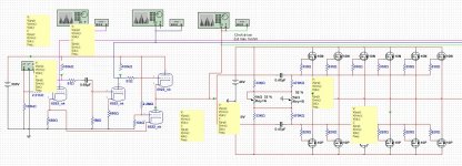
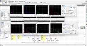
However, I have some Multisim models for Counterpoint power amps set up to learn more about their designs, and I also have The Exicon models avaliable so if interested I quite easily can make a simulation with suitable number of output pairs.
Just like the Hitachi originals Exicon is easy to work with and since they are outside the feedback loop makes it even easier.
I have built several amps based on the Hitachi originals and assume the Exicon's are equally stable and easy to handle with their tempco.
Just like Counterpoint I found that using emitter resistors are very bad for sound quality and I make my designs to avoid the problem as much as possible.
However, I have some Multisim models for Counterpoint power amps set up to learn more about their designs, and I also have The Exicon models avaliable so if interested I quite easily can make a simulation with suitable number of output pairs.
Just like the Hitachi originals Exicon is easy to work with and since they are outside the feedback loop makes it even easier.
I have built several amps based on the Hitachi originals and assume the Exicon's are equally stable and easy to handle with their tempco.
Attachments
Last edited:
Hi William,
Yes, get the oscilloscope first. Even a two channel is good. Analogue!
My strong advice would be to replace any capacitors that have failed, like the heater supply capacitors. There are some for the DC offset, the resistors and zeners run extremely hot, Those are bad for sure. I designed a much better circuit for that. Do not bother replacing the film capacitors. Counterpoint used very good ones, people who say different have zero clue as to what they are talking about. So also, make darned sure the parts you do use fit properly.
Start with the 22K1 value if that is original, try to set the bias per the manual. If you can't, then modification of the circuit is required. I have no experience with these devices in this amplifier. Anyway, allow it to begin to warm up and see where the bias goes - up or down. If it increases you need to reduce the 22K1 resistor in value. If you can get the amplifeir stable at a lower bias current and it sounds good, use the lower current by all means!
Hi flex2,
They did not have oscillation problems that I am aware of. I never had one for warranty with that issue, or out of warranty - ever.
The source resistance is required to make the devices share current. Yes, bad for sound quality but good for keeping the amp running. Being outside the feedback loop is what causes the sound quality issues.
Nice that you're sharing the models. Thanks. I don't drive simulators, so you have me beat there!
Interesting.
Even if it is a simulation I easily can see that the output transistors they used got into oscillation at startup before bias settles. A small source resistor prevent that behavior. I assumed that was the reason for the many broken output stages of Counterpoint hybrids.
Since you know a lot of building electronics, why do you think the output transistors broke down???
Lacking source resistor pushed the transistors into thermal runaway because of positive temperature coefficient???
Regarding the sound quality I do not agree at all. Counterpoints hybrids was among the best and most musical amps I have heard and owned.
If they made them reliable I probably still would own one.
Keeping the output stage outside the feedback loop is a good thing for a hybrid design unless it's very high class A.
Keeping that nasty crossover distortion out of the feedback loop made the tube amplification work much better, and also lower the output impedance enough to be able to drive the input capacitances of the output stage.
Counterpoint run about 4-5mA through the cathode follower and that is not enough to drive eighter the original mosfets nor the Exicon's or Hitachis.
With the feedback loop from cathode follower it barely works.
I would suggest 12mA and not more than 1Kohm output resistance to get a better distortion performance and push -3dB point above 200 kHz.
Regarding using Exicon's as replacement I see that it will keep the amplifier running and get decent result. Similar to the original but with a little more distortion, but not high enough to be detectable at normal listening levels.
Without source resistor the distortion is linear, but with a source resistor mainly odd harmonics is created when pushed into producing crossover distortion.
I assume that's why Counterpoint selected to not use source resistors. They give a harder nastier tone to the sound.
Long time ago a friend of mine built a hydrid design using only two pairs of Hitachi J50/K135 whitout source resistors and outside the loop biased at 100mA each transistor and it sounded very good indeed with most speakers, but run into problems with low impedances. It was too weak for handling impedances below 4 ohms. Four or six pairs would have helped a bit...
That was before I started to build and design myself, but because of that experience I'm not at all afraid of keeping the output stage outside the feedback loop.
One thing I know sound very bad is when creating crossover distortion at the output stage and send it back to the input stage.
Generated crossover distortion MUST be kept out of the feedback loop otherwise you get that "transistor" sound most of us hate to much.
So I wouldn't say that Counterpoint made a bad design by keeping the output stage outside the feedback loop.
For their design it probably was a good choice since it might have messed up the tube amplifier section too much.
I see the reason for their design choices during simulation, but I also see their flaws.
Edit:
Yes, wanted to mention Boulder and their choice to split their amplifiers into two amplifiers used in series.
The main part of the amplification is handled by the first stage that always run in class A (basically no crossover distortion).
That first stage have it's own feedback loop.
The second stage have low amplification (+6dB???) but include the output stage in the feedback loop.
That is a neat way to keep the crossover distortion created away from the main amplification stage and still be able
to have a very low output impedance.
Smart choice of design...
Last edited:
Hi flex2,
Well, okay. I design and repair audio equipment and have for almost 50 years professionally. So I'll answer your comments from that perspective.
Simulators are not real, they do not take into account device variations or real circuit components. They can give you an idea if a circuit may work or not. A huge factor in real performance is PDB layout and only the most (horribly) expensive simulators take that into account. Those are normally used in high frequency work. So what you can easily see is not real.
The reality is this. The output stages do not oscillate before bias is released. I worked on these new, under warranty and continually since. The reason the output stages fail is that the current and dissipation is not shared equally. Having repaired these amps in and out of warranty, I can tell you exactly what the issues are. The outputs without source resistors must be extremely tightly matched. You have no concept how tight the match must be. This was a major issue with manufacture and service. I spent days matching output transistors in a special jig I made. That was the only way to keep these amps together using the original design. Even with source resistors, matching the outputs does improve performance. Same for BJT output stages. This is actual, real life measured and subjective performance.
You can disagree all you want. Counterpoint owners who have heard the modified amplifiers love them even more. I have a waiting list of people for when I have completed the new design. I do retain the "Counterpoint sound", and that took some effort. I did drop distortion by a huge margin. Not one single person prefered the higher distortion original. I also redesigned all the preamps except for the huge ones. Those power supplies are a mess, they are too far gone to fix. They would get an entirely new power supply chassis designed.
I can't understand why you might think running any output stage "open", or outside the feedback loop might be good for sound quality. That is opposite of proved and measured fact. Subjective and otherwise. In a normal amplifier most of the distortion is generated in the output stage. The voltage amp (if it has enough transconductance) always reduces distortion. It also reduces output impedance and you really want this! That is the inverse of damping factor, the ability of the amplifier to control the loudspeaker system. I designed loudspeakers for over a decade professionally. I also did warranty for Nakamichi for years, including the Stasis product. Great amplifiers - on some speaker systems. Guess what design concept is used?
You don't understand how an amplifier works. You need feedback, and if the design is good, feedback will always improve sound quality. Feedback is actually an extremely good thing for more reasons I'll get into.
I don't care what other manufacturers do. They all follow the laws of physics no matter what great story they cook up, or why their designers claim they do things. That's the problem with audio, too many stories that are factually incorrect. Overall feedback is what matters, voltage amp stage transconductance. Yapping about where they put gain and how much is just stupid. Most gain should be in the first stages to reduce noise. It is a system, not a collection of individual stages when you look at it operating. Now allowing only 6dB of corrective feedback only limits performance. The input stage doesn't care what the distortion is, and crossover distortion is not specially destructive or problematic for an input stage. That is merely a story to gain market share. Try talking to a real engineer.
Anyway, I know these amplifiers very well, as does Alan and a few others. They were designed by ear, not from an engineering standpoint. When you apply proper engineering principles, they become reliable and sound better. Imagine that!
Sorry for offending you.
That was not my intention, and I had no idea that you modified the Counterpoint amplifiers.
...and the reason for objecting to the soundquality I haven't heard what you describe as "problem regarding soundquality".
To me all Counterpoint hybrid power amplifiers always have sounded very good indeed.
Thanks for your input regarding matching. Fully get that as a reasonable explanation.
And, yes, simulation is always simulation. It can only give a good hint about performance, but it is a very good start
when developing a project and understand performance.
Regarding the feedback I disagree about what you call "proven and measured fact". I do not think that is the case.
You can for example have an input stage with very low and linear distortion which are in harmony with the signal.
Let's say 0,005% and then you add 0,1% of crossover distortion from the output stage which should be corrected
in all stages. NOT a good thing in my book of audio truths. Cross over distortion should be avoided, not corrected.
But that is MY truth. Yours might differ.
Can't match your 50 years, but have 40 as designer of electronics for what's it worth. Learnt some I hope.
Absolutely not so.You don't understand how an amplifier works. You need feedback, and if the design is good, feedback will always improve sound quality. Feedback is actually an extremely good thing for more reasons I'll get into.
I don't care what other manufacturers do. They all follow the laws of physics no matter what great story they cook up, or why their designers claim they do things. That's the problem with audio, too many stories that are factually incorrect. Overall feedback is what matters, voltage amp stage transconductance. Yapping about where they put gain and how much is just stupid. Most gain should be in the first stages to reduce noise. It is a system, not a collection of individual stages when you look at it operating. Now allowing only 6dB of corrective feedback only limits performance. The input stage doesn't care what the distortion is, and crossover distortion is not specially destructive or problematic for an input stage. That is merely a story to gain market share. Try talking to a real engineer.
Anyway, I know these amplifiers very well, as does Alan and a few others. They were designed by ear, not from an engineering standpoint. When you apply proper engineering principles, they become reliable and sound better. Imagine that!
Maybe you should tell Gryphon or Dan D'agostino have a bad design philosophy and that the must use feedback.
Since they found that NO feedback is the way to get the best musical performance.
- Home
- Amplifiers
- Solid State
- Counterpoint-SA220-pwr to Exicon mosfet 10N20 10P20 TO3