Have a Counterpoint SA-100 in the shop. In addition to all the HV caps having exploded during customer use, I have determined that all of the MOSFETs are bad as well.
There seem to be almost no sources for 10N12, 10P12. Even the Exicon substitutes (which require rewiring and bias circuit mods) are obsolete and non stocked. Then tehre's the BUZ 900D/905D.. no one has them in sufficient quantities to repair this amp. And the ones that are available are about $48 each x 8 pieces.
This is a last ditch effort to find a source at a more reasonable cost. I hate to tell the customer his amp is unrepairable.

https://www.diyaudio.com/community/threads/counterpoint-sa-100-with-exicon-mosfets.94975/
A bunch of unreliable crap imho
A bunch of unreliable crap imho
I think you can use BUZ901/BUZ906. Since my SA-12 lost damage one Mosfet, at the moment I use one pair/channel. Plan to install 2pair/channel with BUZ901/BUZ906 with a little bit modification.

Same pinout as the 10N12? Any bias modification needed to make these work?Those are TO3's ?
I have 2sj55 and 2sk175. Send PM.
/Figge
Am interested to hear your results with the BUZ versions. Pinout config? Bias modifications?I think you can use BUZ901/BUZ906. Since my SA-12 lost damage one Mosfet, at the moment I use one pair/channel. Plan to install 2pair/channel with BUZ901/BUZ906 with a little bit modification.View attachment 1085562
Replace R13,113 from 100K to 22K , Remove R60, R160 then install jumper. Adjust VR1 to 12.5K. Not yet install Mosfet, measure Voltage positive at gate of N-type , Negative at P-type, it should read 1.1VDC if not check R61,R161 or Q1. if voltage it read at 1.1vdc then turnoff. Install mosfet (pin out you have to verify, not difficult to change) target to adjust bias at 50ma. check bias by remove negative rail fuse then install R 0.1ohm measure voltage across R to adjust bias as required, in this case reading should at 5mv. Hope you understand my bad English.Am interested to hear your results with the BUZ versions. Pinout config? Bias modifications?
Last edited:
Thank you for detailing the modifications. Very clear and no problem understanding it.Replace R13,113 from 100K to 22K , Remove R60, R160 then install jumper. Adjust VR1 to 12.5K. Not yet install Mosfet, measure Voltage positive at gate of N-type , Negative at P-type, it should read 1.1VDC if not check R61,R161 or Q1. if voltage it read at 1.1vdc then turnoff. Install mosfet (pin out you have to verify, not difficult to change) target to adjust bias at 50ma. check bias by remove negative rail fuse then install R 0.1ohm measure voltage across R to adjust bias as required, in this case reading should at 5mv. Hope you understand my bad English.View attachment 1086129
My only concern is with the 8A rating of the substitutes.. the original part has a 10A rating. I suppose the addition of .22ohm resistors in the drain circuit may help offset this.
The spec sheets for this and other devices are not a direct apples to apples comparison, making it difficult to determine what the real turn on voltage threshold is for various MOSFETs.
10N12 for example has a Maximum Gate-Threshold Voltage |Vgs(th)|: 4 V.
Whereas BUZ900 has a Gate-source cutoff voltage of max 1.5V. It seems that the original part has a very high threshold and requires up to 4V bias potential, whereas the new part is less than 1.5V. Does that make sense?
The resistors you speak of are at the MOSFET sources, not drains.
I also don't think the original MOSFETs used in this amp are lateral technology devices (Hitachi, Renesas, Exicon, etc.).
I think they're regular switching MOSFETs, so the pinout and biasing are COMPLETELY different.
So, it would be no surprise that device related specs would be very different.
Be careful if you continue to head down this path ...
I have replaced several of the old MosFets (and there is a variety) with IRFP240/IRFP9240, which work without any circuit modifications. I have an SA220 running for over a year without any issues, every single day, from morning till night. Sounds great too. I also have an SA12 which is a mule, which I break regularly.
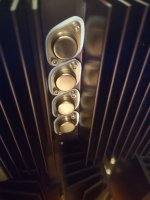
I Love the old TO3s made some "fakes", as visuals are important.
I Love the old TO3s made some "fakes", as visuals are important.
Attachments
On a binote, if anyone wants the old MosFets, let me know, interested in trading for anything cool ((if you dont have anything cool, just let me know what you are interested in....)
That great, please let me know bias value for IRFP mosfet.I have replaced several of the old MosFets (and there is a variety) with IRFP240/IRFP9240, which work without any circuit modifications. I have an SA220 running for over a year without any issues, every single day, from morning till night. Sounds great too. I also have an SA12 which is a mule, which I break regularly.
I Love the old TO3s made some "fakes", as visuals are important.
I run them at 550ma (measure through ammeter mode on Fluke instead of fuse). But they get hot at 550, it is around what the service manual recommends. I recently reduced to 300 just to test sound difference, and they are a little colder, but consume half the power.
I also checked if there was any change in offset on the outputs between 300 and 500ma, and there wasn't, so I think I will install a "Critical Listening" switch for the days it is not just background noise.
Downloading the service manual is worth it!
I also checked if there was any change in offset on the outputs between 300 and 500ma, and there wasn't, so I think I will install a "Critical Listening" switch for the days it is not just background noise.
Downloading the service manual is worth it!
There's at least 2 service bulletins on how he matched his power FETs. DM me if you need them.
From what I can tell looking at the blurry scans of data sheets for 2SJ56 vs 10N12, the pinouts appear to be the same.
Looking at the wiring inside the amp, the wires go to conveniently-labeled PCB with G,S,D markings and the gate pin appears to be the same pin as for the Hitachi lateral MOSFET. There had been talk of the pinouts being different, so I want to be very careful to confirm that indeed the 2SJ/2SK parts have the same pinouts as the ISC original part. Both manufacturers show the same gate, drain, source, 1, 2, 3 clockwise pattern. So should be no rewiring of socket required. Just the mods to the bias circuit. What do y'all make of these data sheets pin charts? Sanity check before I plunge into this.


Looking at the wiring inside the amp, the wires go to conveniently-labeled PCB with G,S,D markings and the gate pin appears to be the same pin as for the Hitachi lateral MOSFET. There had been talk of the pinouts being different, so I want to be very careful to confirm that indeed the 2SJ/2SK parts have the same pinouts as the ISC original part. Both manufacturers show the same gate, drain, source, 1, 2, 3 clockwise pattern. So should be no rewiring of socket required. Just the mods to the bias circuit. What do y'all make of these data sheets pin charts? Sanity check before I plunge into this.
Hexfets (ie IRF series devices) are not very good replacements for lateral gets such as the 2SJ56 or K176. They are thermally not very stable and also less linear, so performance will be greatly compromised. If you decide to use them, the bias circuit needs to be modified for better stability. Thermal drift will be an issue without some sort of temp sensing feedback. Hexfets need to be biased hotter to get into their more narrow linearity range (compared to lateral fets).I have replaced several of the old MosFets (and there is a variety) with IRFP240/IRFP9240, which work without any circuit modifications. I have an SA220 running for over a year without any issues, every single day, from morning till night. Sounds great too. I also have an SA12 which is a mule, which I break regularly.
I Love the old TO3s made some "fakes", as visuals are important.
I disagree, I have used them, on 2 SA20s and 1 SA12 and they work beautifully. One of the SA20s has run all day every day for well over a year. They sound amazing and yep they run hot.....Hexfets (ie IRF series devices) are not very good replacements for lateral gets such as the 2SJ56 or K176. They are thermally not very stable and also less linear, so performance will be greatly compromised. If you decide to use them, the bias circuit needs to be modified for better stability. Thermal drift will be an issue without some sort of temp sensing feedback. Hexfets need to be biased hotter to get into their more narrow linearity range (compared to lateral fets).
Lots of people knock Counterpoint, but completely forget to mention that all of these amps are now over 25 years old, some pushing close to 40years . How many years is reasonable for consumer electronics to work, your Iphone has a useable life of 3 years and you never get bored of spending 1000s to replace it with the latest greatest crap that just happens to be the biggest advertised hit....
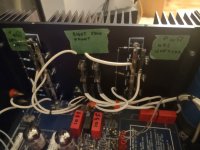
Does anyone have a schematic of the circuit that drives relay K1? I suspect it's not being energized because the voltage across the P and N gates is zero on both channels. I have only gone as far as removing the power MOSFETs and changing R13 and R60 as per the modification mentioned in this thread. The schematic does not show what drives K2. Only that K2's contacts short the gate circuits to ground for mute. I see a 555 timer IC in there, but it's on a PCB and getting the PCB removed to trace it all out is going to be a darned pain in the you know what! Tempted to remove K1, but would have to remove the entire PCB to get to the solder side anyway. Does anyone know if that's a simply delay timer circuit? Maybe when the capacitors failed, it too out the 555 too. It's on a socket so maybe I'll swap it out and see if it energizes the relay after a few seconds.
Oh, and another odd thing I noted is that the power transformer seems to heat up unusually quick. After a minute or so measuring voltages, I noticed the transformer was already warm to the touch. No MOSFETs installed.
Oh, and another odd thing I noted is that the power transformer seems to heat up unusually quick. After a minute or so measuring voltages, I noticed the transformer was already warm to the touch. No MOSFETs installed.
Last edited:
No luck with that delay circuit. I may temporarily pull K1 out so I can test the rest of the amplifier.
The frustrating part is no access to solder side of PCB without taking the whole board out. I already had several wires break off at the bias transistor connections. The PCB traces are VERY fragile. Even gentle desoldering suction lifts traces. So fixing wires that broke is turning into a tedious effort.
The frustrating part is no access to solder side of PCB without taking the whole board out. I already had several wires break off at the bias transistor connections. The PCB traces are VERY fragile. Even gentle desoldering suction lifts traces. So fixing wires that broke is turning into a tedious effort.
- Home
- Amplifiers
- Solid State
- Counterpoint SA-100 MOSFETs Source?