So the Accuphase has the point here.
Yes, for such a simple topology seems to be rather effective. Also, allows using high VAS current, when required - double-VAS handles it with ease (for example, for drivivg the lateral FETs directly ftom the VAS stage)
, this topology shows a very good result. I also like its overall stability, bearing in mind a very simple compensation approach.
yes, its one of the things i found a real Plus. Simple to compensate and always stable. Unlike the tricks and trials and tribulations I see other design topologies go thru to be stable.
THx-RNMarsh
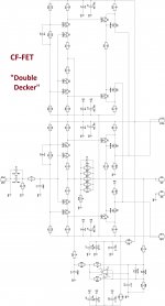
And now to think about to put it on double sided all SMD PCB. Try to find better VAS SMD mosfets which will be cooled down on PCB copper polygon, etc. for some more up-to date solutions. 😉Double Decker schematic "as built".
And now to think about to put it on double sided all SMD PCB. Try to find better VAS SMD mosfets which will be cooled down on PCB copper polygon, etc. for some more up-to date solutions. 😉
I'll think about it
 😀
😀Hi Valery and Jeff
Testing my CFA-CFP boards today and I have some issues. Did either of you do a schematic with voltages or an asc. file? I'm going over my parts again one by one to make sure they are correct but it would also be useful if I had at least a few places I could measure to help locate my error.
Thanks, Terry
I just stuffed mine and ran them. No problems, so no files. What kind of issues are you having?
Hi Guys,
False alarm. I used TL072 instead of TL071. All is well in the universe. I will give it an audio test in the morning.
Blessings, Terry
Edit:
I have about .5V offset on initial turn-on which settles to 0V once the servo gets through. Is this normal?
False alarm. I used TL072 instead of TL071. All is well in the universe. I will give it an audio test in the morning.
Blessings, Terry
Edit:
I have about .5V offset on initial turn-on which settles to 0V once the servo gets through. Is this normal?
Last edited:
Hi Guys,
False alarm. I used TL072 instead of TL071. All is well in the universe. I will give it an audio test in the morning.
Blessings, Terry
Edit:
I have about .5V offset on initial turn-on which settles to 0V once the servo gets through. Is this normal?
Hi Terry - ok, cool. 0.5V before the servo jumps-in is OK for this kind of heavily-symmetric CFA topology. Different tolerances lead to certain disbalance (you never know in what direction) - that's why the servo is very recommended here. It's possible to balance-out the offset with a trimmer, instead of using a servo, but over the time it may certainly drift. With the servo you can just forget about it.
One precaution - it is not recommended to connect/disconnect the input cables with the power on. Such a high-speed, wide-bandwidth amp can have pretty evil harmonics-rich transition noises at the output. Potentially not good for the speakers, in some cases leading to ptotection trip-out.
Hi Valery,
That is good to know. Initially I had the wrong opamp and had. 5v on both boards. I pulled the opamps and still saw the same thing. After I installed the correct servo I watched it closely and that's when I noticed that it took the servo a few seconds to pull it down to 0v.I just wanted to make sure it didn't indicate a problem. I'm looking forward to hearing it. Jeff gave it glowing reviews. It was a fun amp to build and you did a great job on the screenprint so it is kind of a no-brainer. I can see why you and Jeff were surprised when I had issues. May I ask what you set the bias at?
Thanks, Terry
Hi Valery,
That is good to know. Initially I had the wrong opamp and had. 5v on both boards. I pulled the opamps and still saw the same thing. After I installed the correct servo I watched it closely and that's when I noticed that it took the servo a few seconds to pull it down to 0v.I just wanted to make sure it didn't indicate a problem. I'm looking forward to hearing it. Jeff gave it glowing reviews. It was a fun amp to build and you did a great job on the screenprint so it is kind of a no-brainer. I can see why you and Jeff were surprised when I had issues. May I ask what you set the bias at?
Thanks, Terry
Hi Terry,
Optimal quiescent current for this amp is around 35mA per pair - this is a specialty of CFP output stage topology. It runs pretty cool.
Cheers,
Valery
OK, good to know. I did read through the thread again and saw that at one point but just wanted to make sure it didn't change again along the way. I will be listening to them as soon as my soon wakes up. So that I'm clear, that will be 15.4mV across a pair of 0R22 emitters?
One more thing, what is the "BIAS" plug for in the middle of the PCB? Can I just measure across that to set the bias?
Also, I created a spice file for this amp. Something is not quite right because I had to change R9 to 47R to keep it form clipping and the THD is a little higher than I think it should be. Maybe you can take a look and see where I may have an error.
Blessings, Terry
Attachments
I'm looking forward to your impression of this amp. The only one I've found comparable so far has been my Slewmonster with the Kypton-C inputs, but it still has some 60hZ buzz. This one's dead silent.
OK, good to know. I did read through the thread again and saw that at one point but just wanted to make sure it didn't change again along the way. I will be listening to them as soon as my soon wakes up. So that I'm clear, that will be 15.4mV across a pair of 0R22 emitters?
One more thing, what is the "BIAS" plug for in the middle of the PCB? Can I just measure across that to set the bias?
Also, I created a spice file for this amp. Something is not quite right because I had to change R9 to 47R to keep it form clipping and the THD is a little higher than I think it should be. Maybe you can take a look and see where I may have an error.
Blessings, Terry
Terry, you're right - it's 15.4mV over a pair of 0R22 resistors.
BIAS plug is there for connecting an over-current sensor of the control board, but you can measure the above voltage drop right there.
The amp provides the "standard" 29db voltage gain with R9 = 18R.
Actual THD is very low. I will try to play with your model to see what's wrong with it.
Cheers,
Valery
Hi Guys,
The forum seems to be struggling today. I first hooked it up to my scope with an 8R dummy load. for first tests I'm running it at +-36V rails. Sine waves look fine but square waves look good up to about 15khz. At 20khz there is a notch at the front edge of the top. At 50khz it looks like the teeth of a saw on the top and bottom of the squares and it get very distinct at 100khz. If it's important I can take some pictures of it. I played music through it and it sounded fine. Next I hooked it up to a +-50V PSU and now I hear a constant high pitched tone, maybe around 5khz or so. The is with the input shorted. I turned my scope up high and I see a little sawtooth looking signal. I turned the rail back down to +-36V and the tone goes away.
The board is populated per the schematic in post #126.
Any ideas?
Thanks, Terry
Very interesting. A sort of such a low-frequency oscillation? Very rare. What is the amplitude?
I run my build from +/-52V with no problem. My square waves look like the ones in post #89. What is the voltage drop over R26, R29?
I run my build from +/-52V with no problem. My square waves look like the ones in post #89. What is the voltage drop over R26, R29?
- Status
- Not open for further replies.
- Home
- Amplifiers
- Solid State
- Cool simple "clean" CFA