This one fits the title of the thread a little better. 😀
Can this one be tailored to work with the Slewmaster OPS as well?
Blessings, Terry
Hi Terry,
Yes, setting R1, R3 to 43R will give you the VAS current close to 4.7mA, perfectly suitable for driving the Slewmaster OPS.
Cheers,
Valery
Hi Richard - it's not so new then 😀 But it makes me sure I'm going in the right direction 🙂
Thanks for the schematic. Any pdf for the pcb?
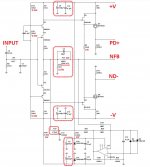
What I don't like about the circuit is (1) resistive VAS loading (2) big gate stopper resistance.
I don't know, I just try to avoid such resistor in VAS or output stage. OS schematics have them as well but almost 1M (yours is much smaller). I will usually try to connect the resistors together (so no ground connection).
The base stopper (470 is too big for my taste), is that to stop oscillation tendency?
Thanks for the schematic. Any pdf for the pcb?
What I don't like about the circuit is (1) resistive VAS loading (2) big gate stopper resistance.
I don't know, I just try to avoid such resistor in VAS or output stage. OS schematics have them as well but almost 1M (yours is much smaller). I will usually try to connect the resistors together (so no ground connection).
The base stopper (470 is too big for my taste), is that to stop oscillation tendency?
Hi Jay,
Thank you for your interest and comments 😉
Schematic is not yet available, this is just the beginning of the project - I will work on it over the weekend and publish here as soon as it's done.
With regards to the points you mentioned above:
1) Those resistors is a common approach to slightly linearize the VAS load. Lateral FETs have got some complex non-linear frequency-dependent impedance. Putting a "linear" resistor in parallel will increase the load, but it will make it a bit more linear at the same time. In case you really dislike this approach, you can simply omit those resistors and see if it brings some benefits - no problem, push-pull VAS will work without them.
2) Those gate stoppers' value was actually determined during experiments/testing within the other project - TubSuMo hybrid amp. 470R resistors with 220pF G-D caps at the N-channel resulted in sustainable stability of the output stage.
Probably, with this front-end (high currents, good stability margins), we can get away with lower values - just a matter of prototyping and testing. Such local instabilities are difficult to simulate.
Cheers,
Valery
Hi Valery
Can you simm fet-bjt VAS pair, mosfets can be a little bit tricky in gain stages.
Regards, L.C.
Can you simm fet-bjt VAS pair, mosfets can be a little bit tricky in gain stages.
Regards, L.C.
Hi LC,
I tried jfet+bjt - not so good as a super pair. Looks like low B-E voltage does not allow the jfet working properly. Nelson Pass uses exactly the same IRF610/9610 "like hell" in gain stages 😀 But not in super-pair configuration.
JFET+MOSFET super-pair appears to be rather linear. This front-end has got not too much of a loop gain - performs primarily based on decent open loop linearity.
We'll see what the prototype is gonna show 😉
Cheers,
Valery
Wow! This is fast )) I will give you some minor schematic improvements within the nearest days 😉
I got motivated.
- It CFA IPS
- It use Fet, even better its use J103/K246 not J74/K170
- It can paired with Fetubsumo OPS and Slew Master OPS
- It CFA IPS
- It use Fet, even better its use J103/K246 not J74/K170
- It can paired with Fetubsumo OPS and Slew Master OPS
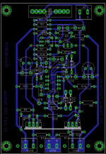
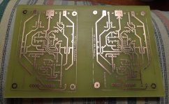
3"x4" double-sided PCB
I'm back home, back to all my tools and systems 🙂
Here is a "standard" size PCB layout.
Gerbers are available on request 😉
Cheers,
Valery
I'm back home, back to all my tools and systems 🙂
Here is a "standard" size PCB layout.
Gerbers are available on request 😉
Cheers,
Valery
Attachments

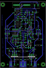
I like it a lot! 
Less packed and one-sided 😎
For +/-35V DC rails, R5 = 20K;
For +/-40V DC rails, R5 = 24K.
Cheers,
Valery
Less packed and one-sided 😎
For +/-35V DC rails, R5 = 20K;
For +/-40V DC rails, R5 = 24K.
Cheers,
Valery
I have ordered a couple of boards for prototyping and testing. Delivery is expected in the end of the coming week 
Hi Terry,
Yes, setting R1, R3 to 43R will give you the VAS current close to 4.7mA, perfectly suitable for driving the Slewmaster OPS.
Cheers,
Valery
Do you have the .asc for this one ? If you do , add the .include for the fet models.
If 43R gives 4.7ma , 39 should = 5+ ?
Most slew IPS's are 5-5.5ma , 4.7 would make the OP's a bit overbiased.
I changed
my first "wolverine" IPS from 4.4ma to 5.3ma (the only exception). Standard 5.3
on all allows direct swaps without bias re-adjustments.
Thanks ,
OS
- Status
- Not open for further replies.
- Home
- Amplifiers
- Solid State
- Cool simple "clean" CFA