Do you have the .asc for this one ? If you do , add the .include for the fet models.
If 43R gives 4.7ma , 39 should = 5+ ?
Most slew IPS's are 5-5.5ma , 4.7 would make the OP's a bit overbiased.
I changed
my first "wolverine" IPS from 4.4ma to 5.3ma (the only exception). Standard 5.3
on all allows direct swaps without bias re-adjustments.
Thanks ,
OS
It's rather sensitive (price for simplicity 🙂). 39R gives around 7mA right away. 42R gives 5.26mA. So, it's possible to put there two resistors in series, as an option.
Ready for testing in the morning.
I will add the input cap first. 😀
Terry, you are much faster than me 😀
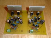
They look great.
Please be careful, as I did not test them yet - try them standalone first - although with no OPS, NFB will create too much load on VAS - anyway, for making sure there are no stability issues and the VAS current is ok, such a test will be good enough.
Hi Valery,
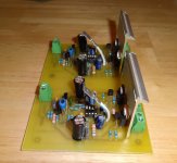
I am going to cool my jets and wait for you to test them. The way my luck has been lately, I'll be chasing ghosts for no good reason other than I rushed in. I just needed a break from trouble the other three amps I'm trouble shooting so I etched these and populated them. They have so few parts I did both of them in about 3 hours. I'm probably going to want to set these up to play with the Slewmaster OPS since I only have the one Tubsumo OPS set and want to use that for the Tubsomo. So I will wait for you to test them and then see what we need to do to get the output low enough to work with the Slew.
Blessings, Terry
Hi Valery,
I am going to cool my jets and wait for you to test them. The way my luck has been lately, I'll be chasing ghosts for no good reason other than I rushed in. I just needed a break from trouble the other three amps I'm trouble shooting so I etched these and populated them. They have so few parts I did both of them in about 3 hours. I'm probably going to want to set these up to play with the Slewmaster OPS since I only have the one Tubsumo OPS set and want to use that for the Tubsomo. So I will wait for you to test them and then see what we need to do to get the output low enough to work with the Slew.
Blessings, Terry
OK, wise decision!
 🙂
🙂Hi Valery,
I am going to cool my jets and wait for you to test them. The way my luck has been lately, I'll be chasing ghosts for no good reason other than I rushed in. I just needed a break from trouble the other three amps I'm trouble shooting so I etched these and populated them. They have so few parts I did both of them in about 3 hours. I'm probably going to want to set these up to play with the Slewmaster OPS since I only have the one Tubsumo OPS set and want to use that for the Tubsomo. So I will wait for you to test them and then see what we need to do to get the output low enough to work with the Slew.
Blessings, Terry
I've abused the slewmaster with anywhere between 4-8ma for IPS. You do have the range for a 7-8ma VAS , easy.
I'm using 390R for the Vbe /R107 , the original schema specified 470R .... which should give adjustment for even higher VAS currents (>10ma).
OS
Green light! 🙂
Gentlemen, start your engines! 😛
But please correct some values according to the next post first.
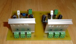
Tested with SlewMonster-based MOSFET OPS (3 pairs) - just had it on a heatsink, easy to hook up.
Some values had to be adjusted - there is a slight difference in currents comparing to the simulation. Set the VAS current to roughly 8mA for this OPS.
Biased to 80mA per output pair. Made compensation a bit lighter.
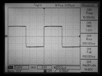
Cool squares, THD /IMD are slightly higher than I expected, but 2-nd harmonic is dominant, 3-rd one is lower and practically no higher harmonics.
Very good phase response (only 4.3 degrees at 20KHz).
Rock stable. At startup jumps to -2V at the output, having it balanced-out by the servo to less than 10mV.
Sounds very natural and detailed. Need to audition it more, but I like what I hear so far.
I also plan to test it with TubSuMo Lat-FET OPS - need to mount it back to the heatsink.
Cheers,
Valery
Gentlemen, start your engines! 😛
But please correct some values according to the next post first.
Tested with SlewMonster-based MOSFET OPS (3 pairs) - just had it on a heatsink, easy to hook up.
Some values had to be adjusted - there is a slight difference in currents comparing to the simulation. Set the VAS current to roughly 8mA for this OPS.
Biased to 80mA per output pair. Made compensation a bit lighter.
Cool squares, THD /IMD are slightly higher than I expected, but 2-nd harmonic is dominant, 3-rd one is lower and practically no higher harmonics.
Very good phase response (only 4.3 degrees at 20KHz).
Rock stable. At startup jumps to -2V at the output, having it balanced-out by the servo to less than 10mV.
Sounds very natural and detailed. Need to audition it more, but I like what I hear so far.
I also plan to test it with TubSuMo Lat-FET OPS - need to mount it back to the heatsink.
Cheers,
Valery
Attachments
-
 DSC03507.JPG322.6 KB · Views: 186
 -
 02-IMD-9-10KHz.JPG208.8 KB · Views: 119
 -
 01-THD-20KHz.JPG183.7 KB · Views: 132
 -
 01-THD-10KHz.JPG190 KB · Views: 133
 -
 01-THD-01KHz.JPG204.6 KB · Views: 153
 -
 DSC03503.JPG345.9 KB · Views: 115
 -
 DSC03502.JPG362.5 KB · Views: 104
 -
 DSC03501.JPG343.7 KB · Views: 109
 -
 DSC03500.JPG336.7 KB · Views: 304
 -
 00 Bode.JPG69.5 KB · Views: 346
As built
Terry, this is first of all for you now, as you already have it soldered.
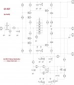
"As built" schematic is attached. Sorry - this one is from DipTrace, better presentation, but different numbering.
Leave R1, R2 as is (22R). It's good to set the VAS current with R8, R9.
R8, R9 = 1.6K -> VAS current = 8mA
R8, R9 = 1.5K -> VAS current = 5.3mA
Other adjustments:
C4 = 33pF
C3 = 220pF
That's it. Have fun! Let me know how it goes and what you hear 😉
Cheers,
Valery
P.S. It's cool to have TO-220 hex-fets as VAS devices. I tried to abuse then even at 40mA - they work, getting just moderately warm 😀
I also love the compensation here - one 33pF lead cap in parallel with GNFB resistor
Ah! One more thing. I've got 4 boards from PCB workshop, instead of 2 (for the price of 2 😉), so I keen to test the paralleled - Accuphase-style - front-end configuration to see what difference it's gonna make. Stay tuned!
Terry, this is first of all for you now, as you already have it soldered.
"As built" schematic is attached. Sorry - this one is from DipTrace, better presentation, but different numbering.
Leave R1, R2 as is (22R). It's good to set the VAS current with R8, R9.
R8, R9 = 1.6K -> VAS current = 8mA
R8, R9 = 1.5K -> VAS current = 5.3mA
Other adjustments:
C4 = 33pF
C3 = 220pF
That's it. Have fun! Let me know how it goes and what you hear 😉
Cheers,
Valery
P.S. It's cool to have TO-220 hex-fets as VAS devices. I tried to abuse then even at 40mA - they work, getting just moderately warm 😀
I also love the compensation here - one 33pF lead cap in parallel with GNFB resistor
Ah! One more thing. I've got 4 boards from PCB workshop, instead of 2 (for the price of 2 😉), so I keen to test the paralleled - Accuphase-style - front-end configuration to see what difference it's gonna make. Stay tuned!
Attachments
I did not match anything, by the way...
That's actually something I'm going to do when I assemble the Fetsomo boards to eliminate some variables. Also my next step in sorting out Tubesomo I think.😀
That's actually something I'm going to do when I assemble the Fetsomo boards to eliminate some variables. Also my next step in sorting out Tubesomo I think.😀
Yes, matching of active devices is a good thing to do. I'm just too lazy sometimes 😛
Let me know if you will need some help with TubSuMo - I can power up the front-end and measure something...
I blew up enough parts on the Slewmonster last night. I'm going to try to tackle Tubesomo today.
OK. Better tackle the front-end standalone until it is fully operational, as expected. It's a VFA, so even NFB works fine with no OPS connected, not overloading the VAS stage. You can connect PD+, ND- and NFB connectors together, and it will be your output. Having it arranged this way, you can measure the VAS idle current by measuring the voltage over one of the VAS emitter resistors (the ones, connected to the rails), and then dividing it by its R value. Precise enough...
CF-FET
Shai Maestro Trio - The Road to Ithaka (2013) - sounds outstanding with this one. Excellent piano, base and drums/cimbals, purely accoustic. At the right volume, the feeling of "presence" is amazing. The brain gets "fooled" 🙂 😎
Sounds very natural and detailed. Need to audition it more, but I like what I hear so far.
Shai Maestro Trio - The Road to Ithaka (2013) - sounds outstanding with this one. Excellent piano, base and drums/cimbals, purely accoustic. At the right volume, the feeling of "presence" is amazing. The brain gets "fooled" 🙂 😎
From good to... great!
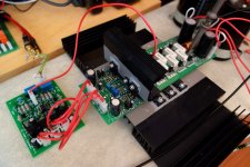
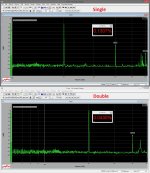
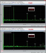
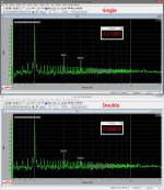
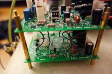
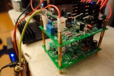
Here comes the Double-Decker 😛
Two identical boards in parallel (positive and negative inputs, both outputs, ground and rails are paralleled). Second board (bottom) is much less populated, as we don't need the second input filter, NFB network, DC servo and load resistors - those ones only present at the top board.
I don't see the difference in noise floor, although it may be limited by my measurement system - it's very low anyway. Some 50Hz products - due to the ground loop in the measurement system - will work on it later.
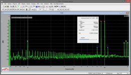
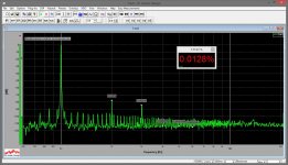
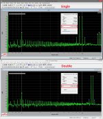
However, THD decreases significantly, especially at the higher frequencies. Harmonics profile is excellent. Again - no matching whatsoever.
Pictures are (after two photos):
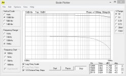
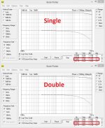
1) Bode plot (closed loop) - note the phase response improvement (20KHz);
2) THD 1KHz - slightly lower;
3) THD 10KHz - around 3.5 times lower;
4) THD 20KHz - also around 3.5 times lower;
5) IMD 14+15KHz - 2.5 times lower;
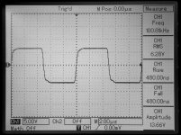
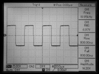
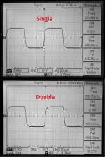
6) Sqware wave responce 100KHz - pretty much the same.
VAS quiescent current is set to 5.5mA per board = 11mA in total.
I ran these tests in combination with the same Hex-FET OPS.
Next test - with Lateral FET OPS from TubSuMo.
Also, more listening will be performed. It's pretty late here now, so I can't listen at any decent volume - although at very low volume it sounds rather cool 😎
I will publish the double- schematic tomorrow. Also, PCB may be updated, so that both "decks" will be placed at the same level - easy.
Cheers,
Valery
P.S. Terry, Didiet - did you try yours? Go for the double-decker 😉
Here comes the Double-Decker 😛
Two identical boards in parallel (positive and negative inputs, both outputs, ground and rails are paralleled). Second board (bottom) is much less populated, as we don't need the second input filter, NFB network, DC servo and load resistors - those ones only present at the top board.
I don't see the difference in noise floor, although it may be limited by my measurement system - it's very low anyway. Some 50Hz products - due to the ground loop in the measurement system - will work on it later.
However, THD decreases significantly, especially at the higher frequencies. Harmonics profile is excellent. Again - no matching whatsoever.
Pictures are (after two photos):
1) Bode plot (closed loop) - note the phase response improvement (20KHz);
2) THD 1KHz - slightly lower;
3) THD 10KHz - around 3.5 times lower;
4) THD 20KHz - also around 3.5 times lower;
5) IMD 14+15KHz - 2.5 times lower;
6) Sqware wave responce 100KHz - pretty much the same.
VAS quiescent current is set to 5.5mA per board = 11mA in total.
I ran these tests in combination with the same Hex-FET OPS.
Next test - with Lateral FET OPS from TubSuMo.
Also, more listening will be performed. It's pretty late here now, so I can't listen at any decent volume - although at very low volume it sounds rather cool 😎
I will publish the double- schematic tomorrow. Also, PCB may be updated, so that both "decks" will be placed at the same level - easy.
Cheers,
Valery
P.S. Terry, Didiet - did you try yours? Go for the double-decker 😉
Attachments
-
 12-IMD-9-10KHz.jpg619.5 KB · Views: 149
 -
 11-THD-20KHz.jpg566.9 KB · Views: 158
 -
 11-THD-10KHz.jpg565.1 KB · Views: 408
 -
 11-THD-01KHz.jpg620.5 KB · Views: 421
 -
 10-Bode-01.jpg203.4 KB · Views: 430
 -
 09-DSC03516.JPG282.5 KB · Views: 443
 -
 09-DSC03513.JPG290.5 KB · Views: 440
 -
 13-DSC03503.jpg692.1 KB · Views: 165
I did not match anything, by the way...
You will get much lower distortion if you match all complimentary types.
I was the first to show this direct-coupled compl-push-pull topology [The Audio Amateur magazine..... now owned by Elecktor magazine]. I ran a line stage at +/- 24vdc and got thd+n of .001% at 22v p-p output into high Z load. At less than that level I couldnt read the thd .... today I could read it with the Audio precision 2722 but have long since given the prototype to a record producer (Water Lilly Records). I used a curve tracer to match the compl transistors.
I think it makes a difference and would recommend matching if you can do it.
THx-RNMarsh
So the Accuphase has the point here.Here comes the Double-Decker 😛

P.S. Terry, Didiet - did you try yours? Go for the double-decker
Not yet. I've been working on some issues with another amp. I just pulled this back out and swapped the parts. Fooled me for a couple minutes there because you changed part numbers between the schematic my boards were designed from and the one you are using now. I'll try giving it a test in the morning.
Blessings, Terry
You will get much lower distortion if you match all complimentary types.
I was the first to show this direct-coupled compl-push-pull topology [The Audio Amateur magazine..... now owned by Elecktor magazine]. I ran a line stage at +/- 24vdc and got thd+n of .001% at 22v p-p output into high Z load. At less than that level I couldnt read the thd .... today I could read it with the Audio precision 2722 but have long since given the prototype to a record producer (Water Lilly Records). I used a curve tracer to match the compl transistors.
I think it makes a difference and would recommend matching if you can do it.
THx-RNMarsh
Yes, matched devices will definitely improve it even further. In fact, K246 and J103 jfets are not really complementary. However, even in such "abuse" conditions, this topology shows a very good result. I also like its overall stability, bearing in mind a very simple compensation approach.
I've got no tracer in hand now, but I'll try to do some simple matching at, say, 5mA drain current for the next prototype 😎
- Status
- Not open for further replies.
- Home
- Amplifiers
- Solid State
- Cool simple "clean" CFA