May I ask why you're intending that Baxandall-like, but passive tone stack instead of a Fenderesque or Marshallesque one with treble, mid and bass controls? I guess you'll have to fiddle a lot with your knobs to get »the« sound that comes automatically with both the alternatives.
Best regards!
Best regards!
That looks pretty good to me!
Thanks! Incidentally, this is also my first time actually drawing a schematic. I like DIYLC, but it's definitely a little limited. I'm going to try ExpressSCH for the next one.
As a very smart man by the name of Roly Roper used to say, there is a time to stop tinkering with the recipe, and just "fling it at the wall and see if it sticks", i.e., build the bloody thing and see how it works. 🙂
I think you have now reached that time. 🙂
The thing is, I actually had already kind of started when I posted. I did all the "demolition" work, and ordered all the parts I would have needed for the first iteration. Now I'm waiting on a few newly required parts, and I got started a little with the dry wiring last night. I don't get a whole lot of time for tinkering - maybe 3-4 hours a week actually at the bench. And I've done very little PTP work (as opposed to turrets), so I'm having to refine some techniques along the way too. So this might be a slow go. But go it will.
May I ask why you're intending that Baxandall-like, but passive tone stack instead of a Fenderesque or Marshallesque one with treble, mid and bass controls? I guess you'll have to fiddle a lot with your knobs to get »the« sound that comes automatically with both the alternatives.
Best regards!
Good question! Couple reasons. First, it's what the donor came with, already wired up, so it's one less thing to mess about with - especially considering that I'm rebuilding the entire preamp, part of the power supply, adding the MV, and replacing every cap that sees DC. Second, I don't think I've ever played an amp with a Baxandall TS, so I'm curious to explore it. If I don't like it, it's simple enough to switch to a Fender blackface or brownface as a future project, and having the CF buffer before it means I can put just about anything I want there without worrying about excessive loading.
Also, and this is admittedly overly sentimental, it's stuff that my dad wired up almost 60 years ago. We had an interesting relationship - not so much troubled, but complicated - and I see this as a symbolic way to hang on to some parts of him, while building my own work on the platform he gave me.
And since this is all relatively low voltage, I don't have to worry about the ancient PIO caps blowing up. 🤣
Got the power supply all soldered up tonight. With no load, I'm seeing 470V B+, right in line with the original schematic.
Ripple at the first node is about 0.04VAC, and at the second it's too low for my meter to detect (and it's a decent meter, a Fluke 115).
Measured the remaining resistors around the 6AN8, and they're mostly good, except the 680K that now reads 1.1M. One of the 47Ks for the PI is at 45.3, the other is at 53.5. I assume that I should replace at least the 53.5, right?
Keep in mind, ripple voltage goes up dramatically with power supply load....no load..Ripple at the first node is about 0.04VAC...
Ripple occurs because the diodes top-up the capacitor with brief pulses of current, while the power supply load drains off cap charge the rest of the time, lowering cap voltage between charging pulses.
So if there's no load to discharge the capacitor, the capacitor voltage doesn't fall in between diode pulses, and you get essentially zero ripple. The more heavily you load the power supply, the more the cap voltage falls in between those charging pulses, and the more ripple voltage you'll see across the cap terminals.
Personally, I don't like noisy old carbon composition resistors, so I would replace both. In this case, you also know that some of them have aged enough to drift dramatically in value, so I suspect none of them is particularly healthy or stable at this point....I assume that I should replace at least the 53.5, right?
But a small imbalance in a phase splitter can arguably be a good thing. A textbook-perfect balanced phase splitter and output stage cancels out all even harmonics created in those devices, but many guitarists like a sprinkling of second-harmonic in the sound. A diyAudio member (Bob Richards) once had some of his measured data on his website about this - basically, unbalancing the phase splitter by about 1 decibel (that's 12 percent) let the even harmonics come back, and to his ears, that was an improvement.
If you want to explore this, you might try, say, 47k and 51k, or even 47k and 56k, in the phase splitter, giving you about 9% or 19% imbalance respectively.
-Gnobuddy
Fun fact: Did you know that if you omit the coupling caps between the PI and power tubes, you can make a pair of EL84s dissipate over 40W into a dummy load, smoking a 10W cathode resistor in the process?
I do ...
I do ...
😀😀Fun fact:...
That burned-out cathode resistor probably saved your output tubes, output transformer, and maybe power supply components too.
Many years ago, when pocket calculators were still very expensive, I built one from a kit - still expensive, just not as much. Then one single dry solder joint in my home-made calculator power supply failed, the zener diode regulating the voltage became disconnected at one end, the voltage soared, and ---poof! No more calculator. 🙁
Stuff like this happens to all of us! Thankfully, you're still intact, and have all your body parts! 🙂
-Gnobuddy
Yeah, I got lucky for sure. I got clever with how I laid out the MV, and in the process just ... missed the caps. And for the life of me I couldn't figure out how the plates went from over 400V without tubes to 241V with them, and the cathodes were sitting all the way up at 47V.
Then the resistor started smoking ...
All is well now. Va 363, Vg2 367, Vk 14. Still pretty dang hot at 31.5mA/11W apiece, but at least I'm pretty sure they won't melt the glass now.
Now to try it with a speaker!
Then the resistor started smoking ...
All is well now. Va 363, Vg2 367, Vk 14. Still pretty dang hot at 31.5mA/11W apiece, but at least I'm pretty sure they won't melt the glass now.
Now to try it with a speaker!
Got her up and running with the original tubes (don't want to fry the NOS stuff if I screwed something up). The test speaker leaves a lot to be desired - it's an 8" alnico from an early 70s Sears 10XL (aka Silvertone 1421) with torn cone repaired with RTV. And it can't handle any real volume. But still ...
Observation #1: Noisy. Lots of buzz - some of which is from the fluorescent lighting, some of which sounds like I've got a ground loop. Need to dig into the grounding scheme. Might ditch the floating ground and go to the chassis. On the upside, the MV silences it, so ... win? Also, all the pots are scratchy (as to be expected), and the tube sockets are dirty.
Observation #2: Holy crap, but this thing has got gain. Likely too much - I should see about cooling off the second stage. Granted, the test guitar has really hot pups, but even so, there's nothing clean above what would be 2 on a Fender. And it gets too fizzy and farty when you get up above 5. My scope arrives tomorrow, so I can see where that's all happening.
Observation #3: Not sure I'm liking the James EQ. Definitely considering doing some variation on FMV. Once I get the noise situation dealt with ...
Regardless - it's alive! Now the fun can begin.
Huh, imagine that. Jumper the star point to the chassis and it goes silent. Maybe I should do that, huh? 🙄
Last edited by a moderator:
I once had a similar issue because of a bad ground to the aluminium front panel of a guitar amp I built - the panel carrying the input jack and all the pots.
The amplifier hummed and buzzed, and I spent some time adding extra RC sections to the power supply and trying other tricks to quiet it. Eventually I discovered the loose ground wire...you can't solder to aluminium (not without special zinc solder, anyway), so the wire was supposed to be trapped under a screw-head, but it had worked its way loose...
-Gnobuddy
Congratulations! 🙂
Thanks! I really can't express my gratitude for your guidance and advice. I knew this would be a learning experience, and luckily I've had no disasters (yet)!
Cleaned the pots and sockets, loaded up the NOS tubes, and plugged into a Weber Texas 12 in a sealed cabinet, and she really came alive. Plenty of clean bark (albeit still a little fizzy at higher gain), and the fartiness disappeared. It was all in that crappy speaker. And with the chassis ground, it's so quiet I can hear the hiss from the few CC resistors I left in place ...
Stuff I want to do before I button up:
- Replace the James EQ with a Marshall-esque TS
- Do some tone shaping if that doesn't resolve the fizziness
- Figure out something to do with the DPDT I'm using for the NFB defeat (which turns out to not do anything really useful)
- Experiment with raising the B+ even higher by jumpering the 110R sag resistor. 6P14P-EV is rated for up to 440 Va and 400 Vg2.
- Experiment with biasing even hotter. 6P14P-EV is rated for 14W, so my 11W is only 83% ... see, though, the only power resistor I have on hand is another 210R ... 105R might be just a *touch* too hot at 400V ... I guess we'll see. And yes, I'll keep an eye on the OT temperature. That's what the laser thermometer is for!
Sound samples and voltage readings to come.
you can't solder to aluminium
Funny you should mention that. This whole thing is aluminum (pardon my Yank spelling 😛). Including all the screws, nuts, and washers. Never seen anything like it. I've had to be super careful not to strip anything along the way.
I put mains earth and signal ground on ring terminals secured to PT mounting screws.
Voltages. Everything seems okay except the PI.
Okay, so about the PI. I'm way off from the schematic:
Questions ...
- Power supply
PT output: 335/335 VAC
B+: 356
Node 1: 349
Node 2: 298
Node 3: 236 - V1a (12AX7)
Va: 204
Vk: 1.385 - V1b (12AX7)
Va: 198
Vk: 1.477 - V2 (6AU6)
Va: 236
Vg2: 193
Vg1: 50.8
Vk: 126 - V3a (6AN8 pentode)
Va: 57.2 (**schematic says 112)
Vg2: 56.2
Vk: 1.63 - V3b (6AN8 triode)
Va: 231 (** schematic says 212)
Vg: 57.2 (** schematic says 112 - directly connected to V3a plate)
Vk: 68.4 (** schematic says 120) - V4 and V5 (EL84)
Va: 343
Vg2: 346
Vk: 13.5
Okay, so about the PI. I'm way off from the schematic:
- Va-k - schematic says 98, I have 164
- Va-g - schematic says 100, I have 173
- Vg-k - schematic says -8, I have -10.6
Questions ...
- Vg-k sets the bias, and -8 to -10.6 doesn't seem TOO outlandish of a difference. Right?
- As long as my input signal is less than 114 Vpp (57 * 2), I won't go into cutoff, right? I haven't measured that because the function generator I bought is a doorstop, and the scope I have incoming that has its own fgen isn't here yet. But I'd be surprised at that kind of a swing coming in.
- Is this because I've changed the input impedance of the next stage? The original is a straightforward 470k. Mine has a 470K pot with the wiper connected to a 1M resistor to ground and a 68k grid stopper. (Yes, the schematic says 1M pot, I'm waiting for the part.) Does that represent a 470k impedance, or does it parallel the 1M for a total of 320k? If so, is that 32% decrease in impedance enough to load down my PI like that?
> Noisy. Lots of buzz ..... Holy crap, but this thing has got gain. Likely too much -
Buzz can be open chassis, bad room, bad joints.... but also TOO MUCH GAIN.
Yeah. A dart-board target for a reasonable g-amp is 20mV input for full output. This one looks like 3mV! So 7X hotter than you need. OK for a head-banger lease-breaker amp, but otherwise like taking the trash out in a top fuel dragster.
The Master makes it less insane but you have to dial that WAY back which is not a happy gain structure. (Like tying the dragster to a tree so your trash doesn't fly into the next town.)
Just omitting the first two cathode caps gets you much of the way there. However long-term you want to loosen-up the NFB on the power section, which will increase gain. I would go as far as skipping V1b and V2. V1a, tone-network, Volume pot, power stage (with 27k raised to 50k-100k).
Attachments
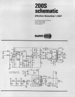
Sunn 200S (BTW: also derived from a Hi-Fi kit, but a big Dynaco) is legendary and may have lessons. The early Sunns were kick-butt large stage amps. This one has second stage biased very cold, does not bother with a buffer. Input sensitivity may be a bit hotter than 10mV of the Fender of that era; Sunn had to do something to stand out. It also has 4X the power of your home-size Heath. Paired with Sunn's hot speakers, these things filled stadiums in days before serious PA (rock PA evolved from stuff like the Sunns).
Attachments
Last edited:
Thanks for all the info! The voltage sequence is really enlightening.
Yup. In this case, it was really down to the lack of earth ground, but for sure it's very, very hot.
That would definitely cool it off. Rather than drop V1b entirely, I think I might convert it into a cold clipper with a 10k cathode resistor, because I do want lots of preamp distortion available even if I don't need the voltage gain.
As for the buffer, I set it up that way in order to be able to experiment with different tone stacks without being concerned about loading up V1b too much (and I had the tube available, so why not?) Besides, I like the weirdness of a pentode CF.
The simplicity is beguiling, for sure. Another thing I'm considering is replacing the 6AN8 recovery/cathodyne with a 12A*7 LTP.
Alternatively, I could put a 6J6 in the 7-pin slot for an LTP, and use the 6AN8 socket for a 12AX7-based tremolo ... hmm.
Man, just when I thought I was getting ready to button this up!
How did you come up with the gain numbers for the TS and the power amp? I'll throw a sine wave at it when I get a chance tonight and see what the actuals are.
Buzz can be open chassis, bad room, bad joints.... but also TOO MUCH GAIN.
Yup. In this case, it was really down to the lack of earth ground, but for sure it's very, very hot.
Just omitting the first two cathode caps gets you much of the way there. However long-term you want to loosen-up the NFB on the power section, which will increase gain. I would go as far as skipping V1b and V2.
That would definitely cool it off. Rather than drop V1b entirely, I think I might convert it into a cold clipper with a 10k cathode resistor, because I do want lots of preamp distortion available even if I don't need the voltage gain.
As for the buffer, I set it up that way in order to be able to experiment with different tone stacks without being concerned about loading up V1b too much (and I had the tube available, so why not?) Besides, I like the weirdness of a pentode CF.
V1a, tone-network, Volume pot, power stage (with 27k raised to 50k-100k).
The simplicity is beguiling, for sure. Another thing I'm considering is replacing the 6AN8 recovery/cathodyne with a 12A*7 LTP.
Alternatively, I could put a 6J6 in the 7-pin slot for an LTP, and use the 6AN8 socket for a 12AX7-based tremolo ... hmm.
Man, just when I thought I was getting ready to button this up!
How did you come up with the gain numbers for the TS and the power amp? I'll throw a sine wave at it when I get a chance tonight and see what the actuals are.
Now that's unusual! 🙂This whole thing is aluminum (pardon my Yank spelling 😛).
My own spelling is a mess - I lived for a couple of decades in a former British colony using British spelling, then for a couple of decades in the USA, another former British colony, but now with it's own spelling. End result, total confusion! Tubes? Valves? Analog? Analogue? Yikes! 😀
I hoped that moving to Canada would help, but it turns out Canada, being so close to the USA, but still maintaining a fond regard for the British, is also caught between two worlds when it comes to English spelling, grammar, and usage. So, for instance, we have Royal City Centre and Staples Center in the same city. One a Canadian corporation, the other an American one!

A Canadian friend who teaches English here in British Columbia told me she tells her students to just pick one version of English - either American or British - and stick to it. I try to follow her advice, but what do you do on a forum thread where everyone else is writing "tubes"? Should I use "valves" and sound pretentious, or use "tubes" and have that nagging feeling like I've made a mistake? 😀
The thing is, bare aluminium is quite reactive, reacts with oxygen in the air, and quickly coats itself with a transparent layer of aluminium oxide, which is an insulator.I put mains earth and signal ground on ring terminals secured to PT mounting screws.
So I've found it difficult to maintain a reliable long-term connection to anything made of Al using ring-terminals and star-washers and so on, particularly if you happen to live near the sea.
About fifteen years ago I discovered a cheap source of surplus small lipo cells (they were pretty rare then), with a major catch: they were bare cells, and the contacts were two little strips of metal foil emerging from the sealed plastic pouch. One of those was bare aluminium (the other was nickel, IIRC).
So I did some hunting around, and I was able to source some special zinc-based solder, and special flux designed specificially for soldering aluminium. Using those two, I was able to solder copper wires to the aluminium terminals of my cheap lipo cells.
In addition to the special materials, you also need a separate soldering iron, or at least a separate tip for your soldering iron - that zinc solder and Al-specific flux contaminates the heck out of the soldering iron tip, and it becomes pretty much useless for ordinary lead-tin electronic soldering after that. At the time, I just bought a dirt-cheap soldering iron from Harbor Freight to use exclusively for soldering aluminium.
-Gnobuddy
Spent a little quality time with a sine wave and the scope this evening.
The smallest signal I can generate cleanly is 20mVpp, so I put that on the input, attached the dummy load, and cranked the volume and MV. Some interesting results. Output of V1a was a clean sine wave at 1.64Vpp.
Output of V1b was a slightly clipped sine wave ... 64Vpp 😱 I'm starting to wonder if it was really such a good idea to goose the B+ to 300V to get all that headroom!
Things get weird at the tone stack. I had replaced the James with a Fender 6G5 stack (Amplifier Tone Stacks - monster.party.hat). And that just messed everything up.
If the treble knob is anywhere above zero, the amp turns into a lovely square-wave generator. To get anything approaching a sine wave coming out of the PI, I had to turn the volume way down and zero the treble. At that point each side of the PI is cranking out 36.8Vpp, and there's 21Vpp on the output. My big honkin' 50W flat wirewound dummy load was almost too hot to touch. I really need to put that in an enclosure ...
So. Next step is to rebias V1b with an unbypassed 10k resistor to get the clipping without so much voltage gain. Probably switch to a Marshall tone stack. And I'm seriously considering the topology change I mentioned before:
The smallest signal I can generate cleanly is 20mVpp, so I put that on the input, attached the dummy load, and cranked the volume and MV. Some interesting results. Output of V1a was a clean sine wave at 1.64Vpp.
Output of V1b was a slightly clipped sine wave ... 64Vpp 😱 I'm starting to wonder if it was really such a good idea to goose the B+ to 300V to get all that headroom!
Things get weird at the tone stack. I had replaced the James with a Fender 6G5 stack (Amplifier Tone Stacks - monster.party.hat). And that just messed everything up.
If the treble knob is anywhere above zero, the amp turns into a lovely square-wave generator. To get anything approaching a sine wave coming out of the PI, I had to turn the volume way down and zero the treble. At that point each side of the PI is cranking out 36.8Vpp, and there's 21Vpp on the output.
My big honkin' 50W flat wirewound dummy load was almost too hot to touch. I really need to put that in an enclosure ...So. Next step is to rebias V1b with an unbypassed 10k resistor to get the clipping without so much voltage gain. Probably switch to a Marshall tone stack. And I'm seriously considering the topology change I mentioned before:
- Replace the 6AU6 with a 6J6-based LTP
- Replace the 6AN8 with a 12AX7 (or 6N2P, I'm cheap), use half for the CF and half for a one-triode tremolo (More tremolo?)
- Home
- Live Sound
- Instruments and Amps
- Converting my dad's Heathkit EA-3 for guitar