Hello All,
A few months ago, I started experimenting with inexpensive ways to monitor fluctuations in household power line voltage.
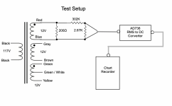
I started by building a test jig consisting of an isolation/step-down transformer (Stancor P-8363), and a voltage divider. The voltage divider consisted of a 302K and 2.67K 1W resistors. I also added a 200Ω 25W resistor to add a load for the secondary. That arrangement gave me a step-down ration of 968.8:1, so a nominal 120VAC to the primary would result in about 125mVAC to monitor.
Next, I looked around for ways to continuously record that voltage. Analog Devices makes a True RMS-to-DC Converter chip (AD736), and even more interesting, an Evaluation Board all stuffed and ready to plug-and-play. Not inexpensive, but exactly what I was looking for. I happened to have in the closet an old strip chart recorder which I pulled out and cleaned up. With all the parts in hand, I lashed-up a test setup as shown in the first attachment.
Attachment 2 shows a portion of a 19-hour recording. The entire recording looks just like this. Visually, the average was about 60 chart lines or 120VAC. The highest voltage recorded occurred around 9:45PM and was 123VAC. The lowest voltage recorded occurred around 6:30AM and was 118VAC. The negative going spikes throughout the recording are probably utilities like sump pump, well pump, furnace, etc., turning on. The largest one I could find had an amplitude of 2.8VAC.
All told, this looks like pretty calm line voltage, as might be expected, since I am located in a rural area. I would be interested to learn what others think.
This experiment says nothing about high frequency hash that might be on the line. While I have the jig set up, I will put the OScope on it and also try to look at the distortion spectrum.
Cheers,
ceulrich
A few months ago, I started experimenting with inexpensive ways to monitor fluctuations in household power line voltage.
I started by building a test jig consisting of an isolation/step-down transformer (Stancor P-8363), and a voltage divider. The voltage divider consisted of a 302K and 2.67K 1W resistors. I also added a 200Ω 25W resistor to add a load for the secondary. That arrangement gave me a step-down ration of 968.8:1, so a nominal 120VAC to the primary would result in about 125mVAC to monitor.
Next, I looked around for ways to continuously record that voltage. Analog Devices makes a True RMS-to-DC Converter chip (AD736), and even more interesting, an Evaluation Board all stuffed and ready to plug-and-play. Not inexpensive, but exactly what I was looking for. I happened to have in the closet an old strip chart recorder which I pulled out and cleaned up. With all the parts in hand, I lashed-up a test setup as shown in the first attachment.
Attachment 2 shows a portion of a 19-hour recording. The entire recording looks just like this. Visually, the average was about 60 chart lines or 120VAC. The highest voltage recorded occurred around 9:45PM and was 123VAC. The lowest voltage recorded occurred around 6:30AM and was 118VAC. The negative going spikes throughout the recording are probably utilities like sump pump, well pump, furnace, etc., turning on. The largest one I could find had an amplitude of 2.8VAC.
All told, this looks like pretty calm line voltage, as might be expected, since I am located in a rural area. I would be interested to learn what others think.
This experiment says nothing about high frequency hash that might be on the line. While I have the jig set up, I will put the OScope on it and also try to look at the distortion spectrum.
Cheers,
ceulrich
Attachments

If you decide to take it further, look into one of the numerous Energy Monitoring chips - for a few dollars you can do something that will monitor both legs of the incoming power as well as the neutral (US anyway) and it will do all the heavy lifting for the math on all of the associated characteristics.
Hal
Hal
The dips are the well-pump fersure. Mine sucks momentary 44A on 500 feet of Aluminum from when it was only a trailer here, and does go below 108V. My street seems solidly regulated at 125V max cuz I've never seen a no-load voltage any higher, and 1V lower on one very hot day.
Remember that most DC power supplies (20th century Audio) respond to Peak not RMS. Last time I looked the difference was minor but people say they see wave-flattening from all the peak-catching crap on the line.
But the actual voltage should not matter unless you are clipping. If you are, there's a problem.
What will you achieve?
Buy a line stabilizer if really needed.
A chart recorder may be available as scrap, but recording it as such will achieve nothing.
If the voltage is off spec, tell the power company, they have equipment to check.
It is their job to supply power at the specified voltage.
Buy a line stabilizer if really needed.
A chart recorder may be available as scrap, but recording it as such will achieve nothing.
If the voltage is off spec, tell the power company, they have equipment to check.
It is their job to supply power at the specified voltage.
HalFoster – Are you thinking of the hardware that connects at the breaker panel, and monitors usage?
PRR – Yah, 44A even for a few ms does get your attention. A one-volt variation seems really good, at least compared to the variation I have on my mains.
NareshBrd – My intent was to see if I could put together a way to continuously monitor and record the mains voltage in my home so I would have a basis for deciding if my audio system would benefit by using a power conditioner. The variation I see in mains voltage does not seem large enough to warrant a power conditioner. The spikes may be another matter, since the AC-to-DC converter has a 360 ms settling time, so they may be quite a bit larger than recorded so far.
I would not expect anyone else to go for a chart recorder, I just happened to have one. I have not investigated it, but DIYing a computerized data logging system is probably very doable.
Yes. I did that at my last home and will do it here when I get bored one day. I had torridial non-contact current transformers around each leg at the breaker box, and a 6" x 6" j-box to the side where the hardware was. I used a Cirrus (CS5467 for both hots, a CS5463 for the neutral) chip for the power sensing with an AVR pulling the results and feeding a LCD display there and a wireless transmitter that fed a receiver at a PC that did logging and graphing etc. No reason for any of it other than it was a fun project and I'm a geek that likes measuring stuff 🤓HalFoster – Are you thinking of the hardware that connects at the breaker panel, and monitors usage?
Hal
Last edited:
When i had a complete b&w darkroom i had difficulty as the intensity and color temp of the enlarger bulb would change with fluctuating line voltage. I got JCP&L to put a logger on the line and lucky ne they changed something at the substation which remedied the issue!
I then got a Beseler/Minolta xenon flashtube enlarger head which was even better!
I then got a Beseler/Minolta xenon flashtube enlarger head which was even better!
Line stabilizers are very common in India, as we have fluctuations.
Relay, or triac, CVT, servo, IGBT...many variants, based on auto transformers for the most part.
Bit surprised you need one in the USA.
Relay, or triac, CVT, servo, IGBT...many variants, based on auto transformers for the most part.
Bit surprised you need one in the USA.
Our lights had been occasionally flickering over the past year or so. Recently, a larger transformer went out and the flickering has thankfully stopped since the repair.
I had never attempted to measure anything however, as I assumed it was without peaks, just dropout.
I had never attempted to measure anything however, as I assumed it was without peaks, just dropout.
The substation which served our small part of suburbia had been outfitted in the 1950's -- now there are many more houses, most with AC. I think they beefed the transformer.Bit surprised you need one in the USA.
Our service provider in NJ is Jersey Central Power & Light -- they were part of the 3 electric utilities which owned "Three Mile Island", the costs of which resulted in beaucoup deferred maintenance through the 1980's.
We downsized when the boys got married and moved out, but we also got a 20kW Generac which runs off natural gas.
That is true here as well, people went from fans to evaporative coolers then A/c, increasing prosperity has made the electric bills affordable for A/c.
So houses with 0.5 kW connections have moved up, 5 - 15 kW is now common.
I see second hand A/c in slums now.
The increased loads mean bigger transmission lines, larger or more transformers, bigger mains breakers, the works.
Evaporative coolers do not work well in areas with high humidity, A/c is dry.
A misuse has been to dry clothes in A/c during the monsoon!
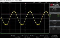
I finally got around to looking at the waveform on an oscilloscope, see attachment 1; and the distortion spectrum using REW and a Focusrite Scarlett, see attachment 2.
From my reading, clipped, or flat-topped waveforms are quite common, and indicate some form of distortion. The distortion spectrum confirms a fair bit of distortion, but I was unable to find any information on what would be considered normal. Does anyone have any guidance on this?
From my reading, clipped, or flat-topped waveforms are quite common, and indicate some form of distortion. The distortion spectrum confirms a fair bit of distortion, but I was unable to find any information on what would be considered normal. Does anyone have any guidance on this?
Attachments

I have used a Fluke VR1710 voltage quality recorder on occasion at my job. It records "Voltage from Line-Neutral and Neutral-Ground, Dips and Swells, Transients, Frequency / Unbalance, Flicker and Harmonics" at user defined intervals, and produces a bunch of nice graphs for analysis.
Unfortunately, the manual has no info as to what levels of each parameter are considered typical or problematic.
I took a look at some old data files and saw the THD levels to be similar to yours at about 2.5%.
I suspect it's highly regional - my data is from northern New Jersey in a light industrial neighborhood.
Some idea of location, neighbors' connections, load level, distance from transformer, single or poly phase connection...would be appreciated.
Type of loads connected (brushed motors are noisy), and so on is also relevant.
And most important, the problem that made you post here in the first place.
Type of loads connected (brushed motors are noisy), and so on is also relevant.
And most important, the problem that made you post here in the first place.
That's better than some I've seen.I finally got around to looking at the waveform on an oscilloscope
Often there are rather high peaks when it recovers.Our lights had been occasionally flickering over the past year or so. Recently, a larger transformer went out and the flickering has thankfully stopped since the repair.
I had never attempted to measure anything however, as I assumed it was without peaks, just dropout.
Of all the things that can be wrong with the mains power, the voltage is probably the most important to monitor.
It's easy to understand why low voltage or brown-outs are a problem but even a slightly high voltage can make trouble as well.... here's my experience.
First one must know the ANSI spec for service voltage in the USA is 120V +/- 5% which is a range of 114V to 126V per leg.
I have a grid-tied solar array on my house and a few years ago the monitoring app was reporting about 1/3 of my panels were not producing any power, which I found strange since the system was quite new. It's all under warranty so I made an appointment with the solar company for a service visit. Before they arrived I happened to measure the line voltage and found it to be 125V in the afternoon and 128V in the late evening. So I called the power company instead and two hours later a crew showed up. They spent the day replacing several capacitor banks in our area to get the voltage down to spec. The next day all my solar panels were back at full production.
To put power back on the grid, the solar inverters need to put out a few more volts than the line voltage, but they too are limited by the ANSI spec of 126V. If the line voltage is too high, the inverters simply shut down.
Sure, a few extra volts on the high side isn't going to damage much, especially these days with wide range power supplies in almost everything, but if you have solar, it could be costing you money.
- Home
- Design & Build
- Equipment & Tools
- Continuous Monitoring of Household Mains Voltage