I'd like to propose another approach to vibration damping. This would involve laying up panels with a minimum of 1/2" F3 felt as an inside layer. The perimeter of the panel would have solid sticking. Imagine a 1/2" thick frame x 1-1/2" wide (or how ever wide you'd need for machining) with a layer of 5-9mm plywood on either face glued to the frame with the felt trapped between. The build up should be glued on an absolutely flat surface and a guy could glue up multiple panels stacked like a press. This would insure all cab members are flat. After machining, exposed edges can be capped with maching veneer or, in the case of BB, left as is. In this case one would make the frame of 1/2" BB as well.
Felt has good vibration damping and is used for machinery mounts. I believe trowel applied materials are too thin to work effectively.
Felt has good vibration damping and is used for machinery mounts. I believe trowel applied materials are too thin to work effectively.
Very little or there would be more interest in it, and it would only be an issue if resonances affected the FR unduly
A poorly damped panel resonance continues sounding after the music has moved on to something else. If it causes a 3dB peak or valley in the frequency response, this is a concern since we will hear that note for some time. It blurs the sound in my experience.
Notice in the video that his CLD construction test panel still is not anywhere close to "dead" (non-resonant) when struck. You don't need a microphone or accelerometer to hear that. So we can ask ourselves, are our cabinet walls any better?
True, but is a sound wave inside a cabinet causing it to vibrate anything like it being struck?
True, but is a sound wave inside a cabinet causing it to vibrate anything like it being struck?
My understanding is it's woofer vibration that primarily excites panel resonances, air pressure inside the cabinet is a lesser effect. So if the driver is playing music containing the frequency of the wall resonance, and that vibration is coupled into the cabinet wall, then the wall resonance is driven. In that case the cabinet walls act as a speaker cone much larger than the woofer. So a tiny wall vibration can cause a big sound. That's the worry.
In theory if you have a sudden impulse in the music, it would be exactly as if there was a physical strike. Like a cymbal strike, but that is mostly higher frequencies than the wall resonances of floor standing speakers. Kick-drum?
I believe you are right there Xandresen, isolating / damping the vibrations from woofer / midbass driver at the interface driver <=> baffle should be an important parameter to consider too.
Andrew Jones (then one of chief engineers at Pioneer) showed in some documents where he used rubber grommets from EAR between a 6" driver and the baffle with very good results resulting in lowered cabinet vibrations and ringing / distorsion. I couldn't track down any good grommets for purchase in my area for my heavier 12" driver. Instead I used what I had available: "The gasket which comes with the TD12 M is more or less only for looks, a plasticized rubber thing, actually too hard to offer optimal sealing. (John Janovitz at AE says the same thing, it offers good looks but is not the best gasket.) So I scrapped it and have / is for fastening of the basket been checking out 2 versions of EPDM foam gaskets + wooden screws. This will give a rather firm, stiff connection so vibrations from the driver are likely to be transmitted to the wooden cabinet. –No good. The connection I will use is a more “floating” one with M6 machine screws going into slightly oversized holes in the cabinet together with a viton o-ring between wood and the basket frame. The M6 nuts + washers inside cabinet will also have viton o-rings for sealing. Reason for viton: Viton has a high loss factor and a low rebound compared in the frequency range of interest compared to other elastomers like EPDM, nitril, silicone, etc so vibrations taken up by the rubber will to a much larger degree be transformed into heat instead of given back as vibrations to the system slightly time delayed. (The diagrams are from a NASA report, in the second diagram "deg C" has been inserted instead of, I believe correctly, "deg F".)"
In case anyone wants to see those NASA diagrams, they are in an old post: Newly built, LCRs with AE TD12 M and Beyma TPL 150H, advices welcomed (Maybe time to dig up that thread from the dead and revitalize it. It has been dead for a long time due to various family reasons.)
ps EAR: E-A-R Aearo Technologies LLC - noise, vibration, shock, damping, sound, control Damping Techniques for noise and vibration Control: https://earglobal.com/media/9891/understandingdampingtechniques.pdf
Last edited:
Well nuts make good vibration isolators. Also magnet mounting can be effective Issues in speaker design - 2
This thread seems to be wandering from the question of whether constrained layer box construction works and how best to implement it. This is separate to the question of isolating the the box from driver induced vibration with compliant mounting. KEF and others tried this in the '70's and abandoned the technique. To my knowledge no-one is still seriously using this technology. It goes against the physics of accurately converting the electrical input into cone motion.
IME the most problematic enclosure vibrations are induced by bass frequencies. When the woofer enclosure is a separate box, which is acoustically isolated from the mid/tweeter box, the problematic enclosure vibrations are confined to the woofer box. Of course this is not an option with a 2-way design. Physically separating the woofer enclosure has the benefit of reducing the intermodulation effects of woofer induced vibration on the mid/tweeter outputs.
There is still the issue of air pressure induced woofer enclosure vibration (box pumping), especially in a sealed bass enclosure. This is where bracing+CLD can make a significant improvement. Bracing raises the enclosure resonant frequencies where the CLD is most effective.
Attachments
How so?It goes against the physics of accurately converting the electrical input into cone motion.
Magnet mounting should be more accurate than chassis mounting
Any motion of the chassis (or enclosure) is counter to the desired pistonic motion of the cone. What is required is mass and stiffness to counter the reaction forces of the cone. Damping mops up the residual motion. No analogy is ever perfect but consider a sprinter using starting blocks compared to starting barefoot on mud.How so?
Magnet mounting should be more accurate than chassis mounting
I completely agree (enclosure mass+stiffness, non-compliant mounting). IME the best woofer mounting system is side mounted opposed reaction cancelling woofers.The driver needs to be sufficiently grounded.
https://www.diyaudio.com/forums/subwoofers/304882-force-cancellation-woofers-3.html#post5706556
This can deal very effectively with the driver induced enclosure vibration. There will still be a role for CLD to handle the internal air pressure induced enclosure vibration.
My apologies to deflecting this thread but I felt a need to try and respond to the compliant mount arguments.
Bon
You have a good handle on the issues and I agree to virtually all of it.
If one uses two woofers then your idea is good, but doesn't work with one. Then you do need a rigid baffle to "ground" the driver as was said. But, this panel should be heavily damped. I used 1 3/4 " of poly boards with CLD between them. Then wrap the back with a well damped box and, IMO, you have as far as you can go with the audible effects along this thread of ideas.
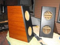
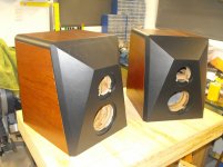
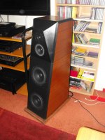
Hi Earl. I appreciate your insights. I agree with your comments about front mounted woofers. I take the mass+stiffness+securely grounded woofers mantra very seriously. In fact, if you look at my post #267, the first photo shows a side view of the front woofer baffle thickness. It is at least 3" (75mm) thick. The fasteners are 5mm hardened steel bolts into rear embedded inserts. It is this type of build that got me looking at other solutions, which don't require such extreme bass enclosures. This is how I arrived at the reaction cancelling opposed drivers. As mentioned previously, even with a stiff enclosure, the internal air pressure flexing can still benefit from CLD.Bon
You have a good handle on the issues and I agree to virtually all of it.
If one uses two woofers then your idea is good, but doesn't work with one. Then you do need a rigid baffle to "ground" the driver as was said. But, this panel should be heavily damped. I used 1 3/4 " of poly boards with CLD between them. Then wrap the back with a well damped box and, IMO, you have as far as you can go with the audible effects along this thread of ideas.
Magnet mounting was also mentioned, which is a different thing. (That's a side argument to what I was saying about the driver being grounded, I think we had a communication breakdown)try and respond to the compliant mount arguments.
I have given magnet coupling quite a bit of consideration in the past and I am not convinced. Firstly from the theoretical point of view, the magnet vibration is of secondary concern. What we are trying to do is enable the cone to accurately transfer the electrical signal into pistonic motion. The magnet is mechanically coupled to the enclosure via the chassis/fixing bolts/baffle interface. Magnet vibrations will be coupled to the cabinet but in an unpredictable nonlinear fashion (distortion). The primary objective is that the cone is the only source of motion and the cone is minimally connected (by design) to the magnet and chassis through the spider and surround. It is the input to the enclosure that we seek to minimise by reaction cancelling. We don't really care what the magnet vibration is doing so long as it does not communicate to the cabinet, which can then be radiated as sound. The place where this vibration will be coupled is the driver frame. It is this coupling from the driver chassis that opposed reaction coupling addresses. If the magnet is vibrating significantly, there is a possibility that it could couple externally acoustically through the cone but I would expect internal acoustic damping could deal with this. Then CLD deals with internal pressure induced flexing.Magnet mounting was mentioned, what do you think about that? (That's a side argument to what I was saying about the driver being grounded, I think we had a communication breakdown)
If you have seen video simulations of tuned-mass-damper systems, you will see two spring coupled masses driven by an actuator with one of the masses making extreme excursions and the other hardly moving. I am speculating that reaction cancelling at the baffle/chassis interface may occur simultaneously with significant magnet motion. I have not done any modelling, it is just speculation.
My other objection is practical. I have not discovered a way to couple opposed driver magnets that I am happy with.
Again, apologies for diverging from the CLD thread. There are a few driver mounting threads in the subwoofer forum.
Would the damping effect the sound output non linearly?Any motion of the chassis (or enclosure) is counter to the desired pistonic motion of the cone. What is required is mass and stiffness to counter the reaction forces of the cone. Damping mops up the residual motion. No analogy is ever perfect but consider a sprinter using starting blocks compared to starting barefoot on mud.
In a simple mass+spring+damping single degree of motion underdamped system, the damping coefficient zeta does modify the frequency of a sinusoidal input, but this is not a non-linear effect, more a frequency downshift and exponential decay. A real enclosure will have many degrees of freedom but each would behave similarly, with different damped sinusoidal responses to a pure sinusoid input. Assuming the cone output is a perfect scaled copy of the input, the total acoustic output would be a superposition of all of these. That is, cone output+all of the damped sinusoidal enclosure outputs (distortion)Would the damping effect the sound output non linearly?
But of course it does ( to add non-linearity to the signal) !
The back wave is the same signal but inverted in phase
It represents 100% error output
The chaotical pressure waves that develop inside an enclosure reflect through the diaphgram
Nothing new under the sun...but there are still people asking questions...😕
🙄
The back wave is the same signal but inverted in phase
It represents 100% error output
The chaotical pressure waves that develop inside an enclosure reflect through the diaphgram
Nothing new under the sun...but there are still people asking questions...😕
🙄
- Home
- Loudspeakers
- Multi-Way
- constrained layer damping with MDF and Ply