Elvee,This is not really a two-terminal CCS, unless you are ready to accept unpleasant tradeoffs.
Here are some examples of 2 wire CCS, some of which can be designed with a -0.3%/°C tempco:
Improved 2W current sources (II)
I have posted a couple of questions in your old Thread.
[LM334 makes quite a nice 5.5 mA current source, works down to 2.0-2.2 volts
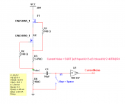
Includes measured Current-vs-Voltage plot of two-terminal (floating) current source.
For 250 volt operation, replace the JFET with one of these very nice Supertex depletion mode Nchannel MOSFETs link to Mouser
~
Includes measured Current-vs-Voltage plot of two-terminal (floating) current source.
For 250 volt operation, replace the JFET with one of these very nice Supertex depletion mode Nchannel MOSFETs link to Mouser
~
Last edited:

Hi Andrew,
Elvee will have notification emails to that effect, so making a post saying you posted somewhere else isn't helpful.
-Chris
I used this setup to measure the current noise of the conventional DMOS cascode current source. The amplifier is the Colin design with noise which ranges 1nV/Rt Hz to a bit lower. The CCS was set for 1mA DC. Frequencies examined 1kHz and 10kHz.
Measured voltage out is 37.2nV/Rt Hz == which if you apply the formula is 3.5pA/RtHz
Measured voltage out is 37.2nV/Rt Hz == which if you apply the formula is 3.5pA/RtHz
Attachments

The LM334 with the addition of a resistor and diode (resistor is 10X Rset, 1N4148) will give you a zero tempco current source. Cascoding increases performance. The 334 does generate some wide band white noise.
I used this setup to measure the current noise of the conventional DMOS cascode current source. The amplifier is the Colin design with noise which ranges 1nV/Rt Hz to a bit lower. The CCS was set for 1mA DC. Frequencies examined 1kHz and 10kHz.
Measured voltage out is 37.2nV/Rt Hz == which if you apply the formula is 3.5pA/RtHz
I should have mentioned, the switched is closed prior to test. This drains the DC voltage to zero at the preamp input. 10uF is overkill as the f3 is ridiculously low.
The best way to operate is to allow the preamp to settle for 4 or 5 minutes, run a noise test with R4 shorted. S1 closed.
Easier to download the data into Excel than write an AP-Basic Macro!
The LM334 with the addition of a resistor and diode (resistor is 10X Rset, 1N4148) will give you a zero tempco current source.
What!??!?!
The LM334 datasheet takes great pains to instruct you NOT to use a gold-doped superfast diode like the 1N4148, whose Vfwd and whose tempco dVfwd/dT do not track the (not gold doped) junctions inside the LM334 IC. Instead, the LM334 datasheet tells you to use the (not gold doped) 1N457 diode. Figure below.
~
Attachments

Although you won't see any improvement in sims with perfect dc rails, in a real world circuit with noise this can have a major improvement in psrr.
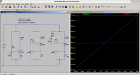
thanks for this tip jerulwoo, here is a graphical comparison showing the improvement vs a couple of other circuits (flatter slope == better)
Attachments
In many applications, a CCS doesn't require floating operation.
In many cases one needs a constant current from a rail, then biasing becomes straightforward and there is no advantage to stick to the dogma of a two terminal current source.
There are truck loads of these CCS inside ICs, that do not float
In many cases one needs a constant current from a rail, then biasing becomes straightforward and there is no advantage to stick to the dogma of a two terminal current source.
There are truck loads of these CCS inside ICs, that do not float
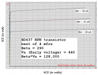
Although you can't tell from the curves in this data sheet this power jfet can make a decent ccs. The few samples I played with gave me ccs of about 1A when I used an 8 ohm source resistor. I believe the current rose less than .1A when I went from 24v to 240v. https://unitedsic.com/datasheets/DS_UJ3N065080K3S.pdf
In many cases one needs a constant current from a rail, then biasing becomes straightforward and there is no advantage to stick to the dogma of a two terminal current source.
There are truck loads of these CCS inside ICs, that do not float
Member cellularmitosis agrees with this; and when you scrutinize the attachments to his post #69, you will see that he is applying and measuring more-than-two-terminal current sources. Study the plot legend in panel 2. There it is.
IMHO post #69 is confusing the issue, making something simple difficult to understand.
I do not invent anything, these are easy to simulate and results I can trust.
I do not invent anything, these are easy to simulate and results I can trust.
mchambin you are right, it is slightly confusing the way these are drawn, as they aren't true "two terminal" sources (because the load is inside the two terminals). I drew them in this way to make it more obvious where the boundaries between each circuit where. Perhaps it would have been better if I had drawn boxes around them instead.
Relatedly, I have started working on a directly-coupled buffer for my headphones which uses this current source: directly coupled class A buffer for low-voltage headphones (work-in-progress)
Relatedly, I have started working on a directly-coupled buffer for my headphones which uses this current source: directly coupled class A buffer for low-voltage headphones (work-in-progress)
OK, I see why you need a high current CCS.
I have a 2 x 10 W Class A that is not made this way.
I like using low power CCS.
For instance as an alternative to bootstrapping. I prefer two small cheap transistors rather than a big cap.
I have a 2 x 10 W Class A that is not made this way.
I like using low power CCS.
For instance as an alternative to bootstrapping. I prefer two small cheap transistors rather than a big cap.
WTF.
What is the purpose of this contraption ?
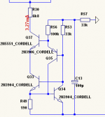
An hybrid of a constant current source and a current mirror, cascoded.
A puzzle, guess all the unknowns !
What is the purpose of this contraption ?
An hybrid of a constant current source and a current mirror, cascoded.
A puzzle, guess all the unknowns !
Nelson Pass's Class-A 20 watt DIY power amplifier from 1977, includes a 2.2 ampere constant current source. You might enjoy studying his circuit design and reading his explanation. Maybe there are some ideas in there, which could be useful in your design work.
link to pdf
link to pdf
- Home
- Amplifiers
- Solid State
- Constant Current Source (CCS) For Audio Applications