I thought I posted this article here but it was in another thread. It seems to me you should read it 🙂 ESP - Heatsink design and transistor mounting
Wow, if I'm ever ill in hospital and I have some days to read something I'll come back to this. War and Peace is shorter. Not to say I'm sure it isn't full of good stuff.
Good news is it's working, the house didn't burn down either.
Bad news is it's only working on one channel. So going to have to find out what else was blown by badly mounted transistors.
Could be the transistors themselves? How do you test a transistor and does it have to be de-soldered from the board first?
These guys were dead. Tested same on and off the board and didn't look good. They seem to be physically damaged, you can see cracks / lumps.
It's not a novel, you don't have to read it in order, there's a handy contents list at the beginning that are links to the different sections. It's ironic that you complain about other peoples attitudes when they are only trying to help.
Your shorted output transistor probably blew the drivers, the TO-220 ones. Possibly other parts before that. 50 v ceramic caps blow often when rail voltage gets loose out the base liune of a shorted output transistor.
You in the first case, measure transistors with a DVM or VOM. 450 to 600 on the diode scale forwards, 9999 or ----- backwards from b toe and from b to c. Forwards is different directions for npn and pnp.
If you have darlington output transistors, 900 to 1400 millivolts forward on the diode scale.
Shorts are bad, 0001 or 0040 millivolts or whatever. Open both way is bad too.
There are better tests, but this is a start.
If the amp were mine, I'd cut a square hole in the bottom using a 3/8" drill and a stanley carbide hacksaw blade. Then I'd put a 3"x8" heat sink with lots of fins down under the chassis, and mount the transistors (with pads) right on the heatsink. Use # 6 or 4 mm screws,and elastic stop nuts so they stay tight. Mount the transistor right where the were before so RF oscillation is not a problem.
Then I would set the amp on its back so the heat flows up. If feet are necessary to keep it from falling over, saw them out of aluminum angle. Screw them to the case with #6 screws.
Use safety glasses using power tools. I buy boxes of SS screws & nuts from mcmaster.com in OH or grainger everywere. Grainger usually ships 2 or 3 boxes for excess freight charges, Mcmaster only has 2 warehouses. Or Fastenal.
I wouldn't read all that, you are not engineering to make the lowest possible cost acceptable product. You are trying to make it cooler. Burning the floor is too hot, that is not a measurement but you don't need much. If you make it too cool, oh well, you wasted $10 on too big a heatsink. Not like you are going to make 100000 of them.
If you don't want to saw stuff, put the fan in as Mr Fahey said. You can use a wall transformer for it, the transformer doesn't have to be inside the case. Any power wires running through a hole in the case, glue rubber hose in the hole to keep it from rubbing on the metal and shorting. Make sure the air has another hole to get out besides the fan inlet.
When I put my 100 mm x 100mm fan on the MMA-875t, I drilled a bunch of 3/8" holes in the cover to give it a way to get in besides the 1" wide grill peavey had provided. Under the fan, the machine work doesn't have to be pretty. The fan has a plastic grill & a filter on it anyway. Filter any other holes to keep the vermin from making a home in there.
I've upgraded the heat sink design on 4 amps now. Even the PV-4 had 4 sets of output transistors in it going by the tech signitures. That is too many. I added a lot of heat sink fins of TO3 pattern to the existing heat sink, drilling & tapping holes for #4 screws.
Last edited:
The bodies of most transistors are live and connected to collector or drain.
So they need insulators.
Mica or silpad pads are often used.
One thing I always do before powering up a new amp is do a short test between transistor pins and heat sink.
Many years ago I once forgot to deburr the mounting holes and all the transistors cut through silpads into burrs on heatsink.
I just run a big drill lightly over the holes to take off the burr edge.
To others here, don't assume that Naim amplifier designs are like any other (i.e. emitter-follower output stages which usually chew up significant current and run quite warm, just doing nothing). These are quasi-complementary designs instead and the bias current is very low at around 30 mA, so only about 7 mV is measured across either power transistor's 0R22 emitter or collector resistor, as appropriate.
So these amplifiers idle only slightly warm and the bottom plate of original products isn't even warm all over for about 30 minutes or until the amplifier is working hard and also, note that the cover needs to be on, right up until you make any adjustments in slow increments because air is the medium of heat transfer here and it doesn't do much transferring, 'takes its time to stabilise too. It can take hours to set similar design amps up to a spec.
So these amplifiers idle only slightly warm and the bottom plate of original products isn't even warm all over for about 30 minutes or until the amplifier is working hard and also, note that the cover needs to be on, right up until you make any adjustments in slow increments because air is the medium of heat transfer here and it doesn't do much transferring, 'takes its time to stabilise too. It can take hours to set similar design amps up to a spec.
Last edited:
It was the 'arctic' paste that I used. It says non-conductive on the side of the tube. But I think we can pretty safely say the transistor bottoms were more than able to pass through the non-conductive paste.
I'm pretty sure it was the screws if You didn't use isolation washers.
It wasn't the screws. The transistors in question have good insulation around the screw holes top and bottom.
Also, since it is now mostly working and the only thing which was changed was exchanging the paste for the sheet that this was the problem.
I also tested the middle leg of the transistor and found it has continuity with the base. So it was shorting via the chassis earth. Hence blowing fuses.
So the next step will be to check the transistors. I can't see anything else which looks damaged.
To restate the obvious about amplifier testing techniques, the simple filament bulb test is one of the simplest, yet extremely powerful to prevent damage to components, especially, output stages.
so with all the outputs being the same type the output must be capacitively coupled ,correct?
if so i would be concerned with the condition of those capacitors.
can you post the schematic?
if so i would be concerned with the condition of those capacitors.
can you post the schematic?
All Naim NAP models were Quasi-complementary but that doesn't mean you can't have balanced power supply rails for 0VDC at the output, like any other post-1970s commercial amplifier, whether it's EF, CFP or QC topology.
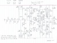
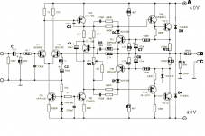
There is no schematic on the 'net for Naim models, apart from an early general schematic that was used for NAP250, which also had regulated power supplies. I attached (I hope) the hand drawn circuit of NAP200, reverse engineered by algar-emi in the long NAP140 kit on Ebay thread. For easier viewing and comparison, there is also the NAP 250 power amplifier board schematic.
Apart from the dual slope current limiter protection that was used in the NAP200 and other late models, the designs are essentially the same, just with more recent semis and component types.
Attachments
thanks Ian that clears it up.
i guess the usual things like emitter resistors on the outputs and the 100r of the driver stage would be next to verify.
i guess the usual things like emitter resistors on the outputs and the 100r of the driver stage would be next to verify.
My quasi comp dynaco ST120 ran quite cool at 1 W/ch in the living room. Just it got very hot & set driver resistors on fire when I tried to use at at 10W/ch at a 3.5 hour church choir rehearsal. I was assuming the OP wants to run his amp at more than 1 W for more than one hour, so he needs to get rid of more heat than a steel case can lose. So he needs to upgrade his cooling power to the air to more than necessary to run 50 W/ch for 1 hour (197? USA FTC watts test standard). The 1 hour watt rating test allowed manufacturers to use their chassis as a heat tank, that would fill up at the end of an hour. Not a heat exchanger to the air.To others here, don't assume that Naim amplifier designs are like any other (i.e. emitter-follower output stages which usually chew up significant current and run quite warm, just doing nothing). These are quasi-complementary designs instead and the bias current is very low at around 30 mA, so only about 7 mV is measured across either power transistor's 0R22 emitter or collector resistor, as appropriate.
So these amplifiers idle only slightly warm and the bottom plate of original products isn't even warm all over for about 30 minutes or until the amplifier is working hard and also, note that the cover needs to be on, right up until you make any adjustments in slow increments because air is the medium of heat transfer here and it doesn't do much transferring, 'takes its time to stabilise too. It can take hours to set similar design amps up to a spec.
I wonder why NAIM is so fiddly on idle current. On the ST120 original or AX6 board in it, I make one idle current measurement to 20 ma, forget it. If I find next year current is 40 ma or 6 ma, the sound isn't noticably different. Nor do I worry about it. Sound wasn't different when I found idle current was 200 ma, but only the fans and extra fins I installed allowed it to run that way for maybe a year. (sense transistor on djoffe idle bias control circuit had failed).
Last edited:
Why fiddly? Most QC designs are built like any other, where the power transistors are mounted on an efficient heatsink of some description. If instead, the whole box and the air virtually sealed inside is used as the heastsink, a load of ballast is added to the thermal response of output stages, hence to the sensing and regulation of the bias current. It makes for an incredibly slow overall response time for the bias compensation when powering up. Early Naim models can take up to 30mins to settle and sound at their best in cool conditions.
Setting the bias level can thus be a fiddly business if you pick the wrong day or forget to keep the temp. up to its normal operating point and stable by closing the box with a cover between adjustments. (i.e. around TR5 in the above NAP250 schematic) Otherwise, if you're designing a QC amp, it's possible to wind up with thermal runaway and meltdown unless you take care to locate that Vbe multiplier transistor in the most appropriate spot.
One thing about QC designs generally; you never just stick TR5 on the heatsink and hope for the best. That makes it a suicide transistor which soon turns the rest of the output stage into a smouldering mess due to thermal runaway too. There can be no optimal bias current setting for a QC design because you have at least 2 different temperature coefficients and base-emitter junction numbers in the upper and lower halves of the output stage.
The best compromise bias control system for QC designs is still likely to be developed by trial and error because ready-to-roll software to do this in simulation has probably never been contemplated. 'Lots of excuses to fiddle with it though.
As you suggest, there can be a wide range of bias settings from as low as 10mA to >30mA per output pair, that work with little variation in distortion over the range. I'm also talking of levels down in the measured 0.002% THD region here with Naim designs and with the example I have in mind of the old entry-level Nait2 model with standard, switching type TIP7XX power transistors.
Measurements were published in an article published by Pinkfishmedia forum members under the title "Modifying Naim Amplifiers" If you need help digging out the article with nice pics, graphs and discussion that covered the making of distortion measurements showing bias setting dependency, perhaps I can do that because it's not straightforward Googling that will get you there and the menu text is microscopic, even on my screen. This the archive and access site: Modifying Naim Audio power amplifiers
The problems there are how much thermal compensation to apply and where to sample temperature? It seems by consensus that the air temperature inside the box represents the overall dissipation and the best indication of whether the amplifier is in thermal control or not. That seems to be true in practice. So a location inside the box and somewhere in the centre of the board, away from hot sinks or resistors may be slow but probably the safest and most appropriate after all .
.
Setting the bias level can thus be a fiddly business if you pick the wrong day or forget to keep the temp. up to its normal operating point and stable by closing the box with a cover between adjustments. (i.e. around TR5 in the above NAP250 schematic) Otherwise, if you're designing a QC amp, it's possible to wind up with thermal runaway and meltdown unless you take care to locate that Vbe multiplier transistor in the most appropriate spot.
One thing about QC designs generally; you never just stick TR5 on the heatsink and hope for the best. That makes it a suicide transistor which soon turns the rest of the output stage into a smouldering mess due to thermal runaway too. There can be no optimal bias current setting for a QC design because you have at least 2 different temperature coefficients and base-emitter junction numbers in the upper and lower halves of the output stage.
The best compromise bias control system for QC designs is still likely to be developed by trial and error because ready-to-roll software to do this in simulation has probably never been contemplated. 'Lots of excuses to fiddle with it though.
As you suggest, there can be a wide range of bias settings from as low as 10mA to >30mA per output pair, that work with little variation in distortion over the range. I'm also talking of levels down in the measured 0.002% THD region here with Naim designs and with the example I have in mind of the old entry-level Nait2 model with standard, switching type TIP7XX power transistors.
Measurements were published in an article published by Pinkfishmedia forum members under the title "Modifying Naim Amplifiers" If you need help digging out the article with nice pics, graphs and discussion that covered the making of distortion measurements showing bias setting dependency, perhaps I can do that because it's not straightforward Googling that will get you there and the menu text is microscopic, even on my screen. This the archive and access site: Modifying Naim Audio power amplifiers
The problems there are how much thermal compensation to apply and where to sample temperature? It seems by consensus that the air temperature inside the box represents the overall dissipation and the best indication of whether the amplifier is in thermal control or not. That seems to be true in practice. So a location inside the box and somewhere in the centre of the board, away from hot sinks or resistors may be slow but probably the safest and most appropriate after all
.Sorry for the late edit but that's 0.02% rather than 0.002% distortion from the Nait2 and about the same as the up-market models.
To find the article, scroll down to the bottom of the acoustica.org page and click on the link there. Look to the left side, grey background menu and assuming you can read it, scroll down to "more Naim stuff" and "bias settings in Naim amplifiers". Click on that and enjoy the glass of wine too.
To find the article, scroll down to the bottom of the acoustica.org page and click on the link there. Look to the left side, grey background menu and assuming you can read it, scroll down to "more Naim stuff" and "bias settings in Naim amplifiers". Click on that and enjoy the glass of wine too.
Last edited:
Well thanks Mr. Finch. It sounds as if the OP wants to avoid this whole idle current setting preheat procedure, and also operate his amp at more than 1 W/ch, he had best install highly competent heat sinks below the output transistors and keep them cool at all times: with a hole cut in the case. Or noisy fans. I'm talking 10 cm by 18 cm x 4 cm thick, with a fin every cm. Then since the amp has the output transistors in the middle of the bottom, the amp in future will have to be set on back or side to allow airflow up. Unless a fan blows in from the back, with exit on the back. Such massive overkill on heatsink would allow the bias to be set fairly cold.
Makes me glad I don't own a Naim 250.
However dynaco did a *****y job of engineering their heat flow on the Quasi Comp amp I do own. Evidence as the reputation of the ST120 for burning the output transistors. Plus the ST120 in the magazine reviews was noted for sounding bad cold. At least the cover is perforated, and there is room under the top to stuff a couple finned TO3 sinks screwed to the plain aluminum angle heat bar the ST120 came with. With 2 fans my ST120 now works 14 hr/day with no heat or bias problems. The ST120 board channel has the djoffe closed loop 20 ma bias control board. The AX6 channel has 2 diodes mounted just above the QC output transistors on a cinch terminal strip for heat sense, sensing the air temp as you suggest in post 55.
Last edited:
When a judge sums up a case he will sometimes have to weigh the evidence to try and determine the correct outcome.
We have 4 things to weigh-up here:
1. Naim originally designed the amp, which is stable as a production item with a fully enclosed case with no ventilation. The case material was aluminium as it is a good conductor of heat. It uses the case as a heatsink. No fins, no fans. Just a substantial volume of aluminium which is mostly under the PCB.
2. The copy amp I have has been working fine for several years using only the thin pressed steel case as a heatsink. Again, no airflow underneath.
3. Ian seems to know something about these Naim amps and says my 6mm aluminium plate under the board should provide ample heat dissipation.
4. On the other side of the balance you seem to be arguing that none of the above is true.
So in total the evidence weighs like this.
1. = it works
2. = it works
3. = it works
4. = it won't work
You could split hairs some more and say perhaps it isn't as clear cut as all this. But it would have to be a lot of hairs and a lot of splitting to make what is substantially true become false.
What really kicked off this whole business a few months ago when I started having problems was changing the speaker cables. I had some fairly cheap thin cables and changed them to 6mm. So that meant the amp had to work harder and this is when it overheated. I lost one channel. Some resistors on the board were burnt-out and there was the scorch mark on my floor.
In the meantime I bought the Chinese version of the Quad 405 and it's really nice, sounds great. It is the fully built version so not relying on me to wire it, build a case and find a suitable power supply. That is more traditional with the same fins along the front you see on the original Quad 405.
Back to the matter in hand.
I've been testing the amp with a multi-meter. I've got 3 PCBs in total so I can make comparisons between them.
Checking between 'ground-in' and 'speaker +' I see resistance on 5 of the 6 channels across the 3 boards. The channel which doesn't work (RH) on the board I'm currently using has continuity between 'ground-in' and 'speaker +'
I've tested many of the components on the right-hand channel and can't find anything different from one side or the other. Just the overall test from ground-in to speaker+ out which shows a short circuit.
I've tested to the best of my ability the large capacitors and 8 of the transistors across all three boards and they all test similar. Some of them have failed on some of the discarded boards but are all consistent on the board currently in use.
You have to bear in mind I slept through all the classes on electronics at school and have learned very little since then so not good with acronyms, not great at carrying out detailed testing. If I can't narrow it down to a likely possible failure point I'll have to give up and order board number 4. The worst part being a wait of several weeks for it to come from China.
All advice much appreciated when it is related to solving the problem.
You mentioned that you are suspending an aluminum plate inside the original steel chassis. Unless you have some means to make air flow across this aluminum plate, you are basically creating an oven to cook your amplifiers in = making things worse.
- Home
- Amplifiers
- Solid State
- connecting transistors to heatsink