From the pictures in post 7 it's not nearly enough. Any air flow is very restricted. JMFahey had some good suggestions. A 5056 aluminum chassis would cool much more reliably and wouldn't cost much.
I used 1050 aluminium for the plate.
Type = 1050, Excellent processability and surface treatability. The most corrosion-resistant of all aluminum alloys. Uses: Heat insulators
Type = 5056, A non-heat-treatable alloy for welded structures. Excellent seawater resistance. Uses: Brake pistons, fuel delivery pipes, airbag inflators
1050 clearly the better choice.
Here's a table: Types and applications of aluminum alloys for vehicles - Aluminum Automobile Technology
in circuit testing to determine the state of the output transistors isn't going to work.
and yes removing or at least isolating 2 of the three transistor terminals is necessary.
seems the omission of mica's or thermal pads was the cause of the fault and i'd say at least one of each output pair is shot.
if the work to test all the components doesn't interest you then your proposal to start fresh with a new board and a new batch of transistors,caps,and resistors is likely to be the best way to go...but even with my 30 odd years as a service tech and live sound tech would not attempt to turn on a device without my "dim bulb tester"!
Last edited:
You're missing the point completely. It doesn't matter how conductive the material is if it doesn't dissipate any heat. To dissipate heat more surface area and exposure to cool air is better. Thermal conductivity means the heat will spread across the material, but says nothing about how it will dissipate heat. Standard heat sink material (not China's finest) is annealed 6061 or 6063 aluminum with fins for extra surface area.
A full U shaped aluminum chassis was mentioned because it will have 3 -4 times more surface area exposed directly to ambient air, not a small sheet stuck in an oven. I suggested 5056 because most sheet metal shops stock this material, it forms well and cuts and taps nicely. 1050, 3003 and other "lower number" or more pure aluminum grades are gummy crap to try to machine, good for breaking taps and stripping out screw holes. Alloys make it much better to work with, but too much alloys (6061) will make it brittle.
A full U shaped aluminum chassis was mentioned because it will have 3 -4 times more surface area exposed directly to ambient air, not a small sheet stuck in an oven. I suggested 5056 because most sheet metal shops stock this material, it forms well and cuts and taps nicely. 1050, 3003 and other "lower number" or more pure aluminum grades are gummy crap to try to machine, good for breaking taps and stripping out screw holes. Alloys make it much better to work with, but too much alloys (6061) will make it brittle.
There is such a type of cooling as a laptop stand with a slow speed fan. When you need more power.
That or something similar, is what I use for my JLH'69 in summer. That's actually now in the lower half of the world and I hate it when it's over 30C and even the volume knob is too hot to grasp.
On topic, I think there is also a missing consideration of the actual power in use. I use only about 5WPC max. output to fill my 7x5m living space. Combine that with a low 5W of quiescent current and you don't really need much heatsink. Turn up the wick to say, 50W of deafening sound though and yes, you certainly will need lots more cooling as the bottom plate heats up much more, according with a realistic output efficiency of about 60%.
Needless to say, if you really were listening to the amplifier at close to maximum power level, you would also be painfully aware of just how hot the baseplate became and how much improvement you needed. As jwilhelm may suggest, it's one thing to have a big, thick and conductive baseplate but if there isn't enough airflow of sufficient speed over its surface to dissipate the heat, it won't do much cooling once its temperature more or less stabilises. I don't need to tell anyone that hot air rises so the airflow parallel to the surface will be virtually static with only small and sporadic up/down currents.
In other words, if you want to get somewhere near the rated power output, you will need the help of aluminium sides, thermally bonded to the baseplate and cover, approximating the original product design .
in circuit testing to determine the state of the output transistors isn't going to work.
and yes removing or at least isolating 2 of the three transistor terminals is necessary.
seems the omission of mica's or thermal pads was the cause of the fault and i'd say at least one of each output pair is shot.
if the work to test all the components doesn't interest you then your proposal to start fresh with a new board and a new batch of transistors,caps,and resistors is likely to be the best way to go...but even with my 30 odd years as a service tech and live sound tech would not attempt to turn on a device without my "dim bulb tester"!
Probably right, most likely I'll buy a new board. I guess in China where these kits originate they're probably teaching electronics in primary school so the fact these things come without instructions they don't see as a problem!
On the plus side, if a similar scenario ever presents itself at any point in the future and I'm required to heatsink some transistors I'll be sure to avoid grounding them! I've learnt that lesson... I think.
A full U aluminum chassis involves a machine shop with a press brake. In my part of the country machine shop owners won't get off their chair for less than $200 + material charge. That is if you show up with a print. Yes, repeat customers get a better price, like the guys that own an electronic repair shop. Not individuals who won't be coming back. Complete chassis with 2 heat sinks on the sides are running $300 on ebay, and that won't fit this board.You're missing the point completely. It doesn't matter how conductive the material is if it doesn't dissipate any heat. To dissipate heat more surface area and exposure to cool air is better.
A full U shaped aluminum chassis was mentioned because it will have 3 -4 times more surface area exposed directly to ambient air, not a small sheet stuck in an oven. .
Whereas the cutting a hole under the transistors with a hacksaw & sticking out finned heatsink 4 cm thick big enough to cover the 4 transistors is about $40 for the heatsink, $5 for a box of screws, $5 for a box of nuts, $2 for the hacksaw, $8 for the stanley carbide blade, $69 for a Dewalt drill motor & $7 for a 3/8" drill. The tools recycle to the next project and the bolts & nuts come in a box of 50, of which 2/3 will be left for next time. Yes, the amp has to sit on its back. Alibaba amp boards are so cheap because they are sold without heatsinks, and the watt ratings they quote are 10 second ratings.
Cutting a 2nd hole for a fan (one exists apparently) costs the drill and drill motor, hacksaw & blade, 3 boxes of screws &nuts @ $5 each (long & short) a $8 fan and two $2 fan grills. Then OP has to live with the noise of the fan.
Last edited:
If you were to go to a machine shop with a job like this you deserve to pay $200. You could likely find a fabricator to do this for $50 though. Tin whackers are starving due to Covid 19 right now.
on transistor testing are the basics of BJT or semiconductor testing a grey area?
it was long ago that an ECG semi conductor replacement guide's additional notes introduced me to the basics for semi-conductor testing.
it was long ago that an ECG semi conductor replacement guide's additional notes introduced me to the basics for semi-conductor testing.
Not sure if anybody remembers this thread from last month.
I've attempted to reassemble the amp again but still not happy with it. Turned it on briefly and the level of hum from it is above what I remember from when this amp was running well so I suspect there's still shorting.
I think the best thing to do with the aluminium heatsink base is to remove it and go back to the design which was working better.
Having said that, 'better' wasn't good enough as it did fail once before kicking off this whole endeavour to try and improve the heat sink design.
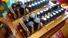
Here is the official NAIM way of doing it, I found a high quality photo of the original job.
It appears to use thermal paste which didn't work well for me last time. But I imagine they've not grounded the aluminium in this design but have it somehow suspended out of contact with chassis ground.
So is there anything obviously wrong with this setup, have they actually tied all 4 transistor bases together on one piece of aluminium underneath? That would mean all transistor bases are touching one another.

I've attempted to reassemble the amp again but still not happy with it. Turned it on briefly and the level of hum from it is above what I remember from when this amp was running well so I suspect there's still shorting.
I think the best thing to do with the aluminium heatsink base is to remove it and go back to the design which was working better.
Having said that, 'better' wasn't good enough as it did fail once before kicking off this whole endeavour to try and improve the heat sink design.
Here is the official NAIM way of doing it, I found a high quality photo of the original job.
It appears to use thermal paste which didn't work well for me last time. But I imagine they've not grounded the aluminium in this design but have it somehow suspended out of contact with chassis ground.
So is there anything obviously wrong with this setup, have they actually tied all 4 transistor bases together on one piece of aluminium underneath? That would mean all transistor bases are touching one another.
Last edited:
so where are you at on this rebuild /redesign?
Not started yet. Looks like I'll have to shape a couple of pieces of aluminium and drill a hole for the bolt. Not a big job. Luckily I have lots of spare aluminium (now).
As the heatsink paste seemed to do the most damage out of everything I tried I decided to stay well clear of paste for this setup.
Seems I got it slightly wrong as I did it from memory rather than looking at the picture just before going to the shed.
The original has two bolts and two pieces of aluminium above (possibly 2 below as well).
Good news is that it works.
I think the lesson to learn here is that trying to use the chassis of an amplifier as a heatsink for the transistors is difficult unless you have a case which is specifically designed for the purpose and the circuit layout.
All the problems of the plate setup were caused by transistors earthing on the heatsink. And with the heatsink being connected to chassis ground this was creating a short circuit.
- Home
- Amplifiers
- Solid State
- connecting transistors to heatsink