Strong & interesting viewpoints! Always great battles on this forum between many knowledgeable people 🙂
OP, good reading for you I hope:
http://www.elmac.co.uk/pdfs/Lord_of_the_board.pdf
http://www.elmac.co.uk/pdfs/desfremc.pdf
more good articles on the same site...
Oh, question: Are you using / designing a PCB? How are you intending to wire your design?
Andy
OP, good reading for you I hope:
http://www.elmac.co.uk/pdfs/Lord_of_the_board.pdf
http://www.elmac.co.uk/pdfs/desfremc.pdf
more good articles on the same site...
Oh, question: Are you using / designing a PCB? How are you intending to wire your design?
Andy
.
<< I should connect ground between A and B, not at A. >>
Then what, if anything, would you connect to point A? If you don't connect anything, then the new connection just becomes a new point A, and everything remains the same.
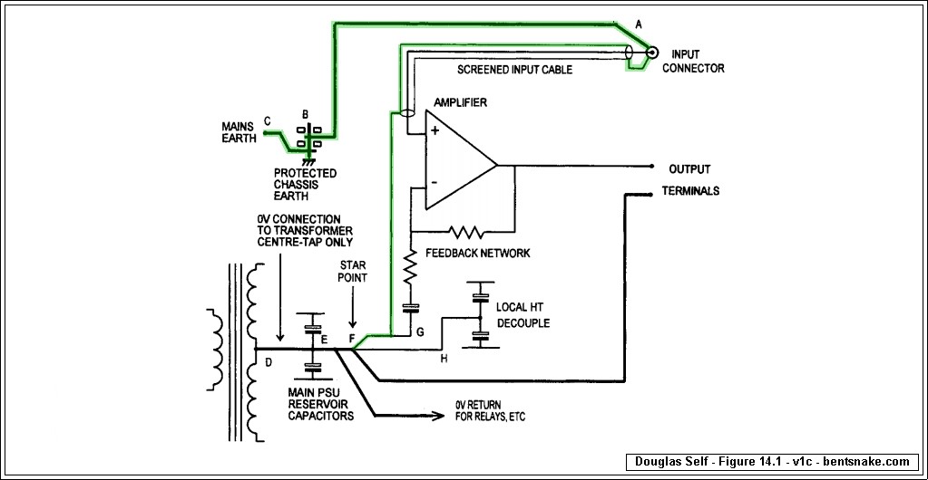
The schematics you show is fig 25.1 of Douglas Self's book on power amplifier design. I do not see a connection to ground near the star point.
I would have liked the metal box to be drawn.
I fear an LC resonant circuit between the low value caps and the inductive component of the electrolytics.<< If I ever used C3 and C4, 100 nF, I would never connect them across electrolytics C1 and C2 >>
But instead you'd...? It would be ever so much more helpful if you'd say how you would connect them. .
The little caps near the rectifier diodes, or nowhere, seems to be more appropriate.
Investigations with an oscilloscope should determine what solution is preferable.
I know Self's articles on amps since day one and I may say this is an area where he is not very precise.The grounding method I offer is based heavily on one recommended by Douglas Self (with others). I post Mr. Self's method for the 10,000th time around here, on the off chance that somebody might look at it this time.
Anyway, I do not see a plain similarity between his ground scheme and yours.
No, it is not a competition. What I try to express is that a kind of "philosophy" should precede the exposition of the methods.I wonder whether you're offering your method as an alternative to mine, or insisting that yours is the only correct method of grounding?
When having put my audio projects in a box, I tested some "provocative" ground layouts, I mean I sometimes add so called "ground loops" (usually considered having deleterious effects) instead of avoiding them or do not exactly follow the star ground "rule".
As my layouts do not produce the slightest hum or buzz, I do not deduce that
I am a master of correct wiring but that the usual rules may not need to be rigorously followed and may even be violated with benefits.
To complicate matters, a good thing at low frequencies may be bad at high frequencies, and inversely. And what we need is a good behavior free of interferences at both.
I think that the fundamental problem of ground wiring has to be well exposed before looking for solutions.
I should connect ground between A and B, not at A.
Then what, if anything, would you connect to point A? If you don't connect anything, then the new connection just becomes a new point A, and everything remains the same.
The schematics you show is fig 25.1 of Douglas Self's book on power amplifier design. I do not see a connection to ground near the star point.
I would have liked the metal box to be drawn.
Thanks for that commentary. However, it has nothing to do with the question asked.
What, if anything, would you connect to point A? If you don't connect anything, then your new connection just becomes a new point A, and everything remains the same.
<< If I ever used C3 and C4, 100 nF, I would never connect them across electrolytics C1 and C2...I fear an LC resonant circuit between the low value caps and the inductive component of the electrolytics. The little caps near the rectifier diodes, or nowhere, seems to be more appropriate.
Investigations with an oscilloscope should determine what solution is preferable.
I understand you to say you'd omit the 0.1uF capacitors at the capacitor bank, and add them (4) across the bridge rectifier.
Decoupling the bridge rectifier is suggested by Mr. Self and others. However, as far as I know this doesn't obviate the need to decouple the capacitor bank also. If you're certain that one is needed but not the other, then I, for one, would very much like to know that, and could you please quote some sort of reference, or give an explanation?
I don't think "I fear an LC resonant circuit..." can really be called an explanation, since the two capacitors are mandated by...well, by pretty much everybody. As I've said more than once, I'm not making this stuff up.
<< Investigations with an oscilloscope should determine what solution is preferable. >>
You didn't already do this? Well, eagerly awaiting.
I know Self's articles on amps since day one and I may say this is an area where he is not very precise.
Anyway, I do not see a plain similarity between his ground scheme and yours.
The green highlighting is intended to show that the two plans are essentially the same. I'm very interested that you don't see this.
Would you please actually state where you see that the plans differ? Just "I don't see it" is not tremendously helpful.
This is, after all, a help forum. It's not a competition.
.
...I have two little ones so I go the safest route on my projects...
Please accept my admiration. In the final analysis, safety is "the way you do it," and doubly so when children are around.
Won't you please explain your "safest route," or better still post a schematic, so we can all benefit?
.
All on perfboard with point to point soldering/wiring.Oh, question: Are you using / designing a PCB? How are you intending to wire your design?
Andy
Of course I know to keep leads short and take care with part placement and so on, remind you all I am use to working with RF design so that is always the first thought on my mind when working with vero/perf 😀
On this forum... yes! 😉
Is your power supply integral to your design, or a separate box?
Can you post up some lovely pictures of what you have so far please?
FWIW I am not a great fan of star pointing. Too much inductance floating about and you have to be VERY careful with what you are doing. It can work beautifully of course, but get it wrong and resulting problems then become very hard to solve.
Good luck! Andy
What, if anything, would you connect to point A? If you don't connect anything, then your new connection just becomes a new point A, and everything remains the same.
http://www.diyaudio.com/forums/chip...us-grounding-methods-designs.html#post4240211
http://www.diyaudio.com/forums/chip...us-grounding-methods-designs.html#post4240286
Sorry, as long as you ignore these posts and do not understand why their remarks are valid, ground schemes can't be discussed further.
Tightly coupling two capacitors of very different values is typically an audiophile recipe and is certainly not used by every electronics engineer.I understand you to say you'd omit the 0.1uF capacitors at the capacitor bank, and add them (4) across the bridge rectifier.
I don't think "I fear an LC resonant circuit..." can really be called an explanation, since the two capacitors are mandated by...well, by pretty much everybody.
I only have the necessary tools to investigate this matter since a few months. Be patient.<< Investigations with an oscilloscope should determine what solution is preferable. >>
You didn't already do this? Well, eagerly awaiting.
.
It appears that another round of name calling and makewrong has come to an end. To nobody's regret, I'm sure.
Speaking for myself, I can say it's been the usual waste of time and effort. Since post #4 some dozen harsh commentators have exclaimed, "Don't do that, that's the wrong way!" But none have said, "Instead do this, this is the right way."
Of course there have been the usual catch-alls, including everybody's favorite, "I can't explain it until you understand it," and the classic, "I have already explained that." It wouldn't be a party without them.
And I suppose some good has come of it all. Probably everybody has reassured themselves that yes, they're as smart as they think they are. Maybe that's something.
But I hope the self-deception stops there, with nothing worse following. Because nothing heroic has happened here, nothing admirable, nothing of importance. It's all been a bunch of eighth grade boys throwing spitballs at each other, hoping the girls are watching, which they're not. Nothing has changed for the better, nothing has changed at all, and if anybody thinks they've made themselves look good, well, nothing got better, so what did you do that was worth doing?
I have to say a pretty sorry state of affairs. Still and all, maybe next time. Next time always has a chance of being better. Maybe next time somebody will say to themselves, "Hey wait a minute, if you say what's wrong, but don't say what's right, then that's not help, that's a drive-by shooting."
A drive-by doesn't accomplish anything because the guy you tried to kill immediately starts trying to kill you back--or his homey does. So the spitballs keep flying, and nothing gets better. Wouldn't it have been measurable easier, demonstrably more useful, to just say, "...and this is what I suggest instead"? Who knows, something might actually get done. Nice change, huh?
.
Last edited:
Post3 gave the correct way to ensure each circuit is correctly wired up.
It was Bent's misleading and often plain wrong advice from post4 and later that led to the need to tell everyone Bent's advice is/was wrong !
It was Bent's misleading and often plain wrong advice from post4 and later that led to the need to tell everyone Bent's advice is/was wrong !
BTW I figured out the feedback problem I had. My own stupidity forgot to wire the filter capacitor directly to the chip pin and star ground. Instead I had it taking a longer path.
So that is one bug down. All feedback is gone now along with major hum issues but I am still learning which method is best to go by for mounting inputs/output to chassis either bonding the jacks or not, and so on.
Lot of reading up to do.
So far so good!
So that is one bug down. All feedback is gone now along with major hum issues but I am still learning which method is best to go by for mounting inputs/output to chassis either bonding the jacks or not, and so on.
Lot of reading up to do.
So far so good!
Sorry if I am not following along that well at the moment but am I correct in assuming this is close to, if not the proper way, to ground as bentsnake posted?...
I tested this method earlier today and it did indeed work well and reduced all hum, but just double checking.
If this is the correct way, then I am assuming the input jack can be bonded electrically right to the chassis so that then chassis gets its ground right where the input jack and the input ac ground wire are correct?
If this is proper, then this will work out nicely since the jacks I want to use for guitar inputs happen to have metal outside sleeves so they can be grounded/bonded right to the chassis.
Last edited:
Because you are building a guitar amp and often the pick-ups and strings are connected to ground there are safety issues that may not normally be a problem with a standard chip amp.
Try connecting the pre-amp input ground to the mains ground/earth and/or chassis to see if this creates hum.
Does the pre have a separate transformer/PSU or is it connected to the power-amp's PSU?
A few photo's would help a lot.
Try connecting the pre-amp input ground to the mains ground/earth and/or chassis to see if this creates hum.
Does the pre have a separate transformer/PSU or is it connected to the power-amp's PSU?
A few photo's would help a lot.
One of the problems with bentsnake's schematic is that it does not work well when you have two or more channels. When you are trying to build a low distortion audio amp it is not the way to go.
Last edited:
NO NO NO!!!
.
As much as I'd like to be an audio guru of international renown, with several books and countless articles to my credit, it's not my grounding scheme, and will everybody please quit calling it that.
The grounding scheme shown in post #32 of this thread (and other posts) is from Douglas Self's "Audio Amplifier Design Handbook," illustration 14.1 on page 402.
The green highlighting is added by me simply for clarity--or anyway I hoped to achieve that. Green is used because electricians say, "Green is ground the world around." But I made no changes to Mr. Self's scheme, not one, none.
That same section discusses grounding and shielding in some detail. Very informative, I think, for those who are willing to learn.
.
.
As much as I'd like to be an audio guru of international renown, with several books and countless articles to my credit, it's not my grounding scheme, and will everybody please quit calling it that.
The grounding scheme shown in post #32 of this thread (and other posts) is from Douglas Self's "Audio Amplifier Design Handbook," illustration 14.1 on page 402.
The green highlighting is added by me simply for clarity--or anyway I hoped to achieve that. Green is used because electricians say, "Green is ground the world around." But I made no changes to Mr. Self's scheme, not one, none.
That same section discusses grounding and shielding in some detail. Very informative, I think, for those who are willing to learn.
.
the screen is actually the signal return of a TWO wire connection.One of the problems with bentsnake's schematic is that it does not work well when you have two or more channels. When you are trying to build a low distortion audio amp it is not the way to go.
As such that screen MUST connect to the Signal Return pad provided on the amplifier PCB.
Now the safety problem.
As shown by D.Self the screen and the two ends where it connects to the chassis and where it to the Main Audio Ground (MAG) will have to pass Fault Current to the Protective Earth if there is a catastrophic failure inside the amplifier.
Can the screen and the two pigtails pass that Fault Current?
But it gets worse. When the two channel amplifier invokes the correct screen connection to the two PCB signal return pads and the traces to reference those pads to MAG, will the soldered connection and the trace pass Fault Current?
Leach has an option to use the Signal input terminal as the local connection to Chassis. He then places on the PCB a Disconnecting Network in the reference trace to MAG (if I remember correctly he suggests a 10r resistor between Signal Return and Power Ground as the low impedance reference connection). Leach then connects MAG to Chassis so that Fault Current can pass to the Protective Earth safely.
Bent can't see this because he does not understand what he is looking at.
He does not understand that EVERY Circuit must have a Route through which current from the Source, arrives at the device and leaves to Return to the Source.
There are no exceptions. EVERY circuit MUST be connected with a TWO WIRE assembly of a size and type appropriate to the signals that need to pass around that connection.
Last edited:
AndrewT, I fully agree with you. But a guitar amp normally has only one channel and so ground loops are not the problem here.
The problem is the guitar, it has all these metal parts that are connected to the return/ground, it should be seen as an extension of the chassis.
Most important is that the mains ground/earth connection to the guitar survives any failure.
The problem is the guitar, it has all these metal parts that are connected to the return/ground, it should be seen as an extension of the chassis.
Most important is that the mains ground/earth connection to the guitar survives any failure.
One of the problems with bentsnake's schematic is that it does not work well when you have two or more channels. When you are trying to build a low distortion audio amp it is not the way to go.
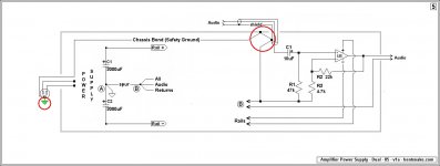
It's Douglas Self's schematic. After that:
Consider, if you will, the points circled in red. These are mechanically different points, but electrically the same point (disregarding conductor resistance).
Making these connections forms the chassis and cable shield (screen) into a continuous shield around the audio circuit and all associated conductors. No gaps, no breaks, a continuous shield, all electrically the same point.
Consider next the circuits that precede and/or follow the shown circuit. Assume (or hope) that these are similarly connected, and therefore similarly shielded.
The result is an unbroken shield around all circuits and all conductors, all electrically the same point.
Now consider the small green triangle. This is the building's grounding system, which really is ground. It's ultimately a ten-foot rod driven into the earth (planet earth) near the building's electric meter.
If you'll imagine this, perhaps you'll see that every audio chassis in a building, and every audio cable shield, is ultimately connected to the same mechanical point--the grounding rod--and that all are electrically the same point (still disregarding conductor resistance).
These are some real-world facts that I thought might be of interest.
(Just to mention it, the building next door has a similar grounding system connected to a grounding rod, and so does the one after that, and the one after that. In fact, all the buildings in the world have a similar grounding rod. This is mandated by all electrical codes, there's an international committee.)
.
Attachments
Bent can't see this...He does not understand that EVERY Circuit must have a Route through which current from the Source, arrives at the device and leaves to Return to the Source.
You speak utter nonsense. Also you use upper case excessively, and your punctuation is atrocious.
On another subject, I don't know why you keep making these personal attacks on me. But then again, a total stranger being rude in a public place is not something to much care about.
But come, should you not strive for some minimal level of courtesy? Just the level total strangers normally show to each other? Because one side makes you grow taller, the other side makes you grow shorter. Can you guess which is which?
.
except that this earth rod does not exist in most installations..................This is the building's grounding system, which really is ground. It's ultimately a ten-foot rod driven into the earth (planet earth) near the building's electric meter.
except that both the neighbours probably don't have an earth rod either.If you'll imagine this, perhaps you'll see that every audio chassis in a building, and every audio cable shield, is ultimately connected to the same mechanical point--the grounding rod--and that all are electrically the same point (still disregarding conductor resistance).
These are some real-world facts that I thought might be of interest.
(Just to mention it, the building next door has a similar grounding system connected to a grounding rod, and so does the one after that, and the one after that. In fact, all the buildings in the world have a similar grounding rod. This is mandated by all electrical codes, there's an international committee.)
.
- Status
- Not open for further replies.
- Home
- Amplifiers
- Chip Amps
- Confused over various grounding methods and designs