could the baffle tilt a bit? https://i.imgur.com/iOKDK8S.jpg
Yessir, it could🙂 , the fold & layout would look different than what we see in that image though ..
Question about K-slot setup
Freddi ,
Does the driver's baffle being tilted in relation to the slot need to be a requirement for a functioning K-Aperture?
Or can the driver's baffle be completely parallel with the aperture's panel and still work alright?
Has anyone experimented with this?
Freddi ,
Does the driver's baffle being tilted in relation to the slot need to be a requirement for a functioning K-Aperture?
Or can the driver's baffle be completely parallel with the aperture's panel and still work alright?
Has anyone experimented with this?
Karlson, using coaxial and fullrange type, tilted it to direct the highs up towards the listener - the inclined plane tapered front chamber was supposed to dump energy faster- - a slot should "work" parallel to a baffle.
Karlson, using coaxial and fullrange type, tilted it to direct the highs up towards the listener - the inclined plane tapered front chamber was supposed to dump energy faster- - a slot should "work" parallel to a baffle.
Freddi ,
I am still still thinking about how we could work out a way to employ the K-slot for more consistent upper midrange dispersion on a Super Planar type cabinet .... The only thing i keep coming up with is the Paraflex including the slotted front panel, it is just difficult to model (a job for Akabak i am thinking) ..
Last edited:
I think MDF is not that much different from gingerbread crackers in terms of strength and resistance to moisture 🙄 ..... It is probably all made in the same factory anyhow .. . 😉 by Elves of course ..
LOL!
Nice one. 😀
Progress
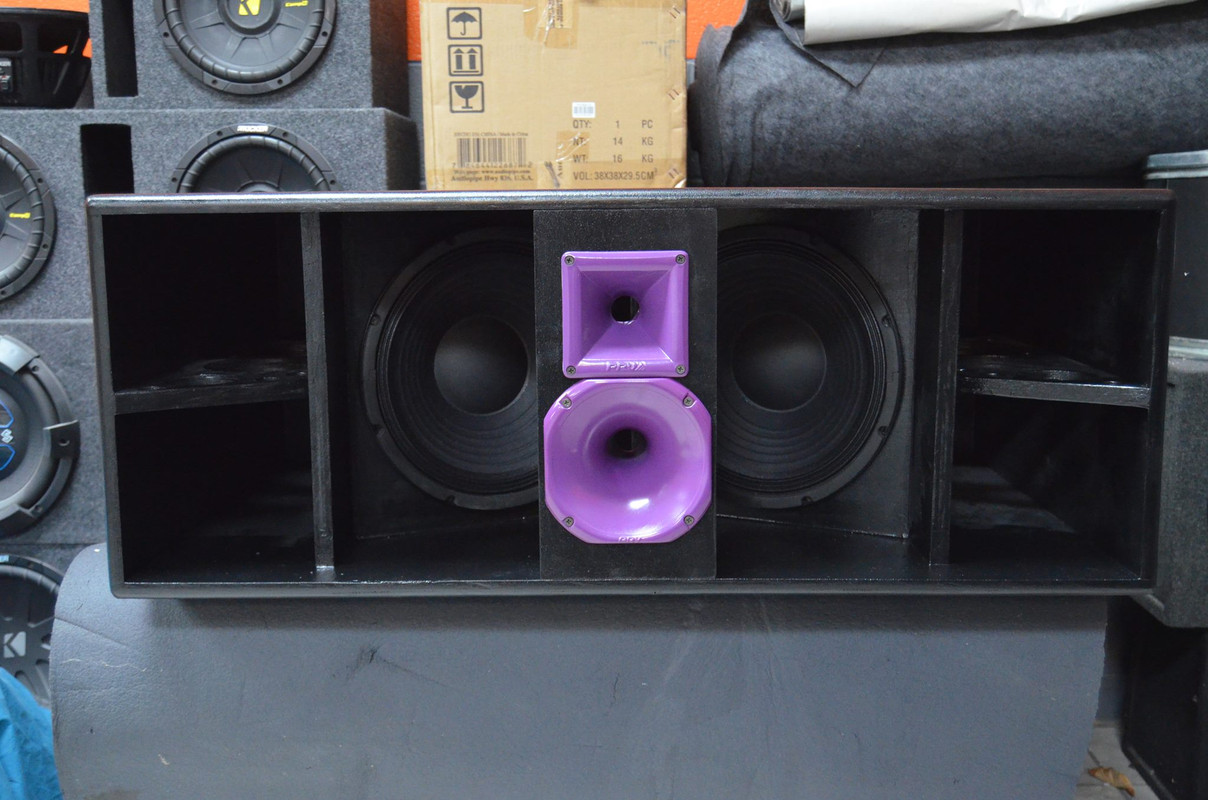
The new Super Planar club tops build project is coming along well ... 🙂
Mr Vansickle has the horns painted and just now loaded up the Dayton PA310s .
.
The new Super Planar club tops build project is coming along well ... 🙂
Mr Vansickle has the horns painted and just now loaded up the Dayton PA310s
.An externally hosted image should be here but it was not working when we last tested it.
Last edited:
Very nice body of work Mathew Morgan. I haven’t been over to subwoofer forum for some time now so just saw your thread for first time. Neat stuff here.

The top look very robust Matthew. The only thing I do not like are the HF horns. I find it a weird combination of HF drivers. I would rather use a 2" CD driver or dual 1.4" CD horn with a waveguide. I got some idea's for prototyping I will work out the next couple of months.
Is this the one with a better designed front chamber?
Any measurements?
Is this the one with a better designed front chamber?
Any measurements?
Very nice body of work Mathew Morgan. I haven’t been over to subwoofer forum for some time now so just saw your thread for first time. Neat stuff here.
Xrk ,
Thank you so very much
 This means a lot to me because I have always admired your work
There is more to come!
The top look very robust Matthew. The only thing I do not like are the HF horns. I find it a weird combination of HF drivers. I would rather use a 2" CD driver or dual 1.4" CD horn with a waveguide. I got some idea's for prototyping I will work out the next couple of months.
USRFobiwan,
Right, this cabinet would be wonderful as a two-way with a heavy duty compression driver, i totally agree .... I have my eye on that Eminence N314T-8 for the future 😀 ... In such a deluxe 2-way model the 12" drivers would also have more motor force, increased power handling, and higher Xmax ratings....
For the low budget version of the 2-way tops i would like to try 12" drivers with very hot upper mids allowing for a higher crossover point , so that a less expensive set of compression drivers can be used ... For a very low budget version we may even try the PA310s with HIGH-Q LPF to give us a nice increase in the upper mid presence before an abrupt cutoff . . 🙂
There are definitely a few things i would like to explore but since i am not doing any of the building currently I don't have total control over what drivers are being used ....... It just depends on what the builder has on hand, and what their budget is , or what they can source for the right price ...
Is this the one with a better designed front chamber?
Any measurements?
Compared to the original single-path spanned-driver Super Planar Club Tops these symmetrical split-path layout tops don't have quite as much dedicated resonant air-mass in the front chamber, but they shouldn't need quite as much since their fundamental tuning is much higher.......
Measurements (happening over the weekend hopefully) will confirm whether or not the response ripple & hole associated with the FbX3 harmonic have been alleviated to an acceptable degree ....... We can still extend the divider panels forward by a few more inches if it turns out that we need more dedicated resonant air mass in the front chamber ...
very beautiful design.
Regarding CD horn, hasn't it narrow dispersion?
Thank you🙂, and yes that is correct, the PRV horns that are being used here have narrow dispersion........
Other patterns with different horns can be chosen, it just depends on what your application calls for ..
Multiple narrow dispersion compression driver horns arranged with sufficient splay angle would be a cool solution, or even large Constant Directivity horns with a wider dispersion angle (like these big EV HR series horns that i have) would be great, but those options would probably require that the compression drivers and their horns be placed into their own dedicated topper cabinets and stacked on top of the Super Planars .... Some people might not find it visually appealing but i think it would look impressive!
 😱
😱 
Last edited:
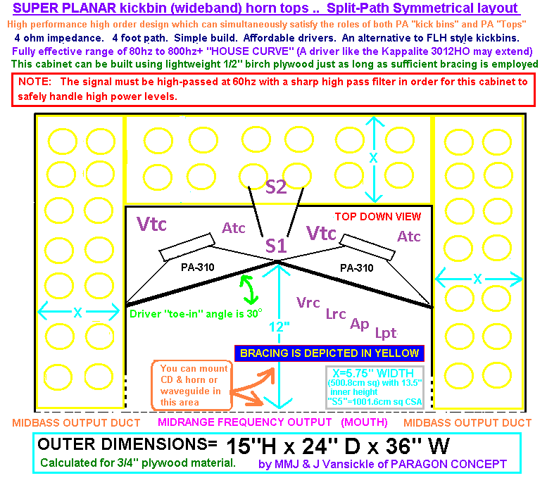
Throat chamber (Vtc / Atc) can be used on Super Planar tops!
Fidstang,
I added a throat chamber along with all of the Hornresp designations so you could see how they apply to the Super Planar tops ..
Of course that throat chamber and duct section could be formed in many different ways , this was just an easy and quick way for me to demonstrate it by making the simple modification to one of our current Super Planar tops sketches 🙂
This cabinet with the throat chamber simulates just fine, performance in this model doesn't seem to be altered very much (when compared to a cabinet without throat chamber, same tuning, same internal volume and drivers) .....
.....
No air particle velocity issues here because the duct is added near the very low velocity end of the QW resonator where there is mostly pressure but not much air particle velocity within the passband. This constriction could act as a choke to filter the much higher frequencies up in the range where the sound being emanated by the front of the cones should already be dominant anyhow .......... Due to the LPF effect i suppose It may be possible that this modification has the potential to clean up or flatten the mid or upper response at least a little bit in real world operation ... It is worth a shot
 ... It shouldn't hurt to build them this way if someone really wanted to .. .
When modeling these, could you please explain why you choose to not treat the volumes in front and behind the drivers as volumes? I'm having a hard time wrapping my head around the Vrc and Lrc being 0.1, instead of modeling this as you would a Cubo design, with the volume behind the drivers (Vrc) and making S1=S2. Then using the Vtc and Atc to capture the volume in front of the drivers, instead of using the Ap and Lpt I kept in the pic.?
Fidstang,
I added a throat chamber along with all of the Hornresp designations so you could see how they apply to the Super Planar tops ..
An externally hosted image should be here but it was not working when we last tested it.
Of course that throat chamber and duct section could be formed in many different ways , this was just an easy and quick way for me to demonstrate it by making the simple modification to one of our current Super Planar tops sketches 🙂
This cabinet with the throat chamber simulates just fine, performance in this model doesn't seem to be altered very much (when compared to a cabinet without throat chamber, same tuning, same internal volume and drivers)
..... No air particle velocity issues here because the duct is added near the very low velocity end of the QW resonator where there is mostly pressure but not much air particle velocity within the passband. This constriction could act as a choke to filter the much higher frequencies up in the range where the sound being emanated by the front of the cones should already be dominant anyhow .......... Due to the LPF effect i suppose It may be possible that this modification has the potential to clean up or flatten the mid or upper response at least a little bit in real world operation
... It is worth a shot ... It shouldn't hurt to build them this way if someone really wanted to .. .
Last edited:
What is Tymphany thinking?
Some guys were talking about this one on Facebook the other day ...
Sorry GKH, but i have to share my critique of this thing .... I just can't resist...
Well .... It is interesting for sure just because it is unusual and strange, and i do like "strange" sometimes😉 so don't get me wrong BUT over 500 grams of moving mass on that 15" driver, high inductance yet mediocre motor force, and not nearly enough linear Xmax to keep up with it's extreme power handling ....
Just what were they trying to accomplish with this?
Unless i am missing something about this driver it doesn't seem particularly useful or cost effective ....Maybe they made a mistake on their data sheet?......
It seems that the folks at Tymphany were determined to make something really incredible and it just didn't work out, as if the designers went on strike halfway through the process ...... Bob from the HR department and good ole "Cheeky" Karen
 from Accounting had to finish the design work on this one ..... We ended up with this overpriced mudmotor ...
This new woofer may be interesting...
Some guys were talking about this one on Facebook the other day ...
Sorry GKH, but i have to share my critique of this thing .... I just can't resist...
Well .... It is interesting for sure just because it is unusual and strange, and i do like "strange" sometimes😉 so don't get me wrong BUT over 500 grams of moving mass on that 15" driver, high inductance yet mediocre motor force, and not nearly enough linear Xmax to keep up with it's extreme power handling ....
Just what were they trying to accomplish with this?
Unless i am missing something about this driver it doesn't seem particularly useful or cost effective ....Maybe they made a mistake on their data sheet?......
It seems that the folks at Tymphany were determined to make something really incredible and it just didn't work out, as if the designers went on strike halfway through the process ......
Bob from the HR department and good ole "Cheeky" Karen from Accounting had to finish the design work on this one ..... We ended up with this overpriced mudmotor ...
Last edited:
- Home
- Loudspeakers
- Subwoofers
- Compound loading 6th order quarterwave "Super Planar" horns and pipes concepts/builds