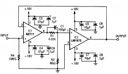
Thanks, I'll definitely follow these leads (the link works). Reviewing some of the composite amp papers I have, I haven't found anything similar to what this schematic shows. Maybe I expected it to jump out and bite me, so I'll have another go at it. The original article does have a table showing several alternate values for the filter, but I'm unsure about what does what eg how is the R2 value determined? The math was probably too deep for a RE article; it could be too deep for me. I figured I could sub some "tweak values" and analyze the o'scope results.
It seems that MyRef projects have a little op-amp for pre, an LM3886 for output and negative feedback from the pre all the way to the output. Maybe I read it wrong, but it looks like you'd want to check it out. It looks like Howland Current Pump.
Sorry for my ignorance but I just discovered the concept of "composite amplifiers".
For audio power amplifiers the idea, in short, seems to be the use of a high-quality OP-AMP for control of a less good power amplifier such that the overall performance is dominated by the high-quality OP-AMP?
I found an AD711/LM1875 design on the net.
Is it correct that the power amplifier needs a high bandwidth to keep the overall bandwidth reasonably high?
Is it possible to use a class D power amplifier or is the bandwidth to low to keep the "outer loop" reasonably fast? Does the inherent 300KHz-600KHz ripple perturb the outer regulation loop?
Thanks to anyone who provides a reply after so many years of hibernation.
Last edited:
I've been making composite amps for quite a few years now. See my Modulus-series of amplifiers.
The basic idea is to perform error correction on a power amp by using the loop gain of a precision opamp. The topology has been used for decades to get DC precision on high-speed opamps. At the bottom of my Modulus-86 page, you'll find a list of references that you'll probably find insightful.
Composite amps are relatively straightforward to get to work if the output stage has much higher bandwidth than the control opamp. For audio applications, the output stages are pretty low bandwidth compared to the control opamp, so stability becomes a serious challenge. It can be done, though, as I show with the Modulus-86 and beyond.
Tom
Tom, thanks a lot for taking time to reply.
I was already aware of Neurochrome/Modulus and your amazing THD results. When you wrote ...uses an LME49710 precision audio op-amp to perform error control on an LM3886 power amplifier… my precision power supply background left me a hint. The net brought the term “composite amplifier” and I wanted my experience with bandwidth of multiple loops confirmed for amplifiers.
I appreciate people who manage to work their way into perfectionism and, nevertheless, offer products most can afford. Your results are impressive. The Modulus-series is a reference.
But, for me it will be interesting to see what a single high-quality OP-AMP can do for a more mediocre power IC. Just to get some experience with the potential of the concept.
Mange tak.
Probably best to start a new thread and let this one die.
As far as using it on something like a TPA3118 or so, well, if you look at the overarching topology of the Hypex modules, then we're not too far off. It's going to be pretty tough to get much extra loop gain into the outer loop, even deep into conditional stability and will require pretty high order filters to pull the loop gain out of the outer loop over a narrow bandwidth if you don't want to waste your time.
IMO, this may be a case where an error correcting amplifier will work much better to decouple the respective bandwidths. (acknowledging that they're tied together AND that I have essentially zero experience doing so)
Thanks a lot, DPH.
I have never seen a straight forward composite amplifier with a class D power stage so I guessed there was a reason.
I may try with class A/B.
I have never seen a straight forward composite amplifier with a class D power stage so I guessed there was a reason.
I may try with class A/B.
Following DPH's suggestion to look into error correction, you might be interested in this: http://www.diyaudio.com/forums/soli...in-composite-op-amp-circuits.html#post2415805
Thanks a lot, DPH.
I have never seen a straight forward composite amplifier with a class D power stage so I guessed there was a reason.
I may try with class A/B.
Start perhaps with a headphone amplifier! Can get pretty fast output buffers/amps that give you some bandwidth to start!
+1 for a headphone amp. Get it running in the simulator first. Do beware that the high-speed buffers are excellent at picking up FM radio and analog TV stations. 🙂
Tom
Tom

I dunno, those circuits just "look too simple" to work, considering all the gain and phase stuff, it can be hard enough to keep ONE op-amp from oscillating.Anybody build any of these?
I am tempted, since I have the chips.
But I suppose all that could happen is the magic smoke comes out.
I've read a claim (somewhere on diyaudio years ago) that for a general op-amp, inverted has less distortion because the + and - inputs stay at essentially the same voltage relative to ground (and the power inputs), whereas moving the inputs up and down as in non-inverted changes the bias slightly, this'n'that, making more distortion.Are there any advantages of one or the other? Inverted, non-inverted?
Headphones amp are almost "too easy" otoh so I'm not sure it's really worth going there. It's no big deal to find a high output very fast one to put inside the loop of a slower, higher precision one. The challenge of composite power amps is to manage a big slow amp as the output.
That's why I linked the error correction post by jcx
That's why I linked the error correction post by jcx
I've read a claim (somewhere on diyaudio years ago) that for a general op-amp, inverted has less distortion because the + and - inputs stay at essentially the same voltage relative to ground (and the power inputs), whereas moving the inputs up and down as in non-inverted changes the bias slightly, this'n'that, making more distortion.
That's known as common-mode distortion. It's a thing for some older opamps. More modern parts perform better in the non-inverting configuration as they don't have any/much common-mode distortion and, thus, benefit from the extra 6 dB of loop gain that is available in the non-inverting configuration.
Tom
Another thing to think about is to build a discrete front end with diff in diff out for driving a bridged class D arrangement.
Well well, someone's stealing all my fun thoughts 😉
It's been something ruminating in my head for some time, and I was thinking discrete primarily because it might be easier to control the gain structure, but I assume you're using it to good effect in your latest bridged setup? (and it's a different part to the OPA1632?)
It's been something ruminating in my head for some time, and I was thinking discrete primarily because it might be easier to control the gain structure, but I assume you're using it to good effect in your latest bridged setup? (and it's a different part to the OPA1632?)
Yep. I'm putting the loop gain to good use in the MOD686.
You can set the LME49724 (or OPA1632 if that better suits your fancy) up for unity gain if that's what you want.
Tom
You can set the LME49724 (or OPA1632 if that better suits your fancy) up for unity gain if that's what you want.
Tom
- Home
- Amplifiers
- Chip Amps
- composite amplifiers