Are you going to test if oscillating or not , or compare the sound of your circuit with a standard bridge ?
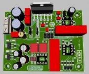
AUDIOPHONICS APD85 Amplifier Module Mono LM3886 100W / 8 Ohms - Audiophonics
AUDIOPHONICS APD85 Amplifier Module Mono LM3886 100W / 8 Ohms - Audiophonics
Are you going to test if oscillating or not , or compare the sound of your circuit with a standard bridge ?
AUDIOPHONICS APD85 Amplifier Module Mono LM3886 100W / 8 Ohms - Audiophonics
I will definitely test if it oscillates. I want to understand how this ticks in real life and get to know it intimately.
I'm in for the learning and the fun that for actually getting a finished product; the product is more of a bonus if I do things right.
New topology, BOM reduction
After some super helpful hints from the eevblog forum, I gave it a shot at a simplified topology where there is only one LME49710 for each paralleled group (so each half of the bridged amp).
I think - if functional - that this could result in less distortion as the 49710 can correct a whole group now.
Ideally - one 49710 should control the whole bridge amp - but I don't know how to do that.
Anyway, like this I managed to reduce the BOM by eliminating on LME49720 and surrounding passives.
I'll also give it another shot at a different PCB to wire the power traces behind the LM3886 chips and connect them to the heat sink with some metal bars (1 cm wide for example), This can result is removal of some electrolitics but more importantly - a better ground layout.
Here's the new schematic: amp-LM3886-composite2 - EasyEDA
The previous one was updated with some corrections:
- zobel network are 90 deg apart now
- ground plane for the signal ground
Let me know what you think
Would you mind linking to the EEVblog thread? I'm curious what they had to say.
Tom
Sure. Here it is: Composite amplifier: LM3886 + LME49720 - Page 1
New topology, BOM reduction
I finished the schematic and PCB for the second version.
Here it is:
amp-LM3886-composite2 - EasyEDA
There are several improvements over the previous version:
- Lower BOM (one LME49720, several big caps, lots of passives)
- Proper signal ground planes both top and bottom
- Better power traces: power goes at the top and the VCC/VEE are overlapped. For bridged amps, VCC and VEE go out of phase always.
- Slightly smaller PCB
- No TH component flipped
The disadvantage is that the trace going from the 49710 to the 3886 is longer now.
In simulations all this seemed ok.
Here are some screenshots:
Nah... Ready for prototyping maybe. 😉
Best of luck on the meeting with reality. I hope it goes well.
Tom
Tom, as you said composite amps are difficult to stabilise and my guess is that you would have had to compromise on the bandwidth to maintain adequate stability margins. Someone with your knowledge could easily design a discrete power amp with impressive specs, which i am certain would be as well received, so I hope you wont mind me asking as to what made you select the lm3886 composite high power solution path?
Jean, I thought of something similar only last week. I replaced the servo with capacitors in the feedback loops and something like a DRV134 in front so that there is no need to make two different amp boards.

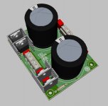
Here is the PSU I intend to use with this amp:
psu-LM3886-composite - EasyEDA
View attachment 740584
The traces to the decoupling capacitors will carry high currents and are too long. Try to bring the small decoupling cap close to the large ones, avoid 'T' shaped tracks to and from the large caps. I would recommend against R5 but if you use it, its solder pad should be immediately after the positive pad of C3 to make sure it gets the proper decoupled supply after C3.
Sure. Here it is: Composite amplifier: LM3886 + LME49720 - Page 1
Sweet. Thanks.
Here is the PSU I intend to use with this amp:
I suggest routing VCC/VEE as pours rather than traces.
Tom, as you said composite amps are difficult to stabilise and my guess is that you would have had to compromise on the bandwidth to maintain adequate stability margins.
There are basically three fundamental ways of stabilizing a feedback loop:
- Reduce loop gain
- Dominant pole compensation
- Phase lead/lag compensation
Someone with your knowledge could easily design a discrete power amp with impressive specs
Thank you. I'm glad you think so. I may create such a design in the future. Time will tell.
what made you select the lm3886 composite high power solution path?
Convenience. The LM3886 is well recognized in the DIY community and can be teased into providing world class performance if used within a composite loop. It's very DIY friendly - basically plug-n-play. There's no bias to adjust. No over-current protection loops to go unstable. No drama around output devices. It just works.
That said, the LM3886 is not without quirks. I cover some of them in my Taming the LM3886 series. I need to get the remainder onto my website before they disappear out of my brain.
Unfortunately, the LM3886 also comes with a bit of "chipamp stigma". That's really unfortunate as it can really sing if treated right. And, honestly, the transistors don't know whether they're inside an IC or inside a discrete package.
Tom
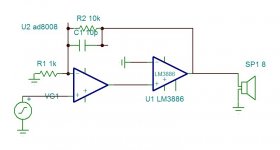
May be you are not a knowledge with documents AN-1192 . As you dealing for educational purpose , I advise to learn also using CFA op amps . The AD8008 is very simple . You can tie it to the +input of the open loop 3886 with -input grounded and the LM3886 gets transformed into CFA with the AD8008 inputs .
Hi Jean,
A few thoughts I had while following your project... . With the necessary disclaimers. I'm not an expert... .
When using a voltage divider to make sure the opamp clips before the 3886, you could also consider a slower opamp like the opa1688, which has a similar slew rate as the lm3886. This might simplify the stabillity question. I's be interested to understand the impact on noise performance of the voltage divider.
for the input you could consider an opa1632. Downstream of the opa1632 you can built identical bridge halves.
With the 1632, you have an input stage. You could make this clip before the lm3886 clips by putting anti parrallel diodes between the two outputs. Again, I'd be interested to understand what the impact on THD and noise would be vs the voltage divider.
Attached a Tina spice sketch...
Best regards,
Rob
Attachments
Done! I keep forgetting to use pours... I did the same for the new amp PCB btw.I suggest routing VCC/VEE as pours rather than traces.
Thanks for the advice.
I thought about doing a discreet amp at first but after reading on this forum the challenges of doing a good amp with a LM3886 I imagined it cannot be easier going discreet.Convenience. The LM3886 is well recognized in the DIY community and can be teased into providing world class performance if used within a composite loop. It's very DIY friendly - basically plug-n-play. There's no bias to adjust. No over-current protection loops to go unstable. No drama around output devices. It just works.
Stability, protections, PCB design are full of traps. Unless one is doing discreet for the learning experience of course.
Hi for all,
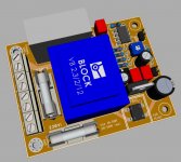
thats my small project, perhaps can I give some good /or bad...🙂/ ideas....
thats my small project, perhaps can I give some good /or bad...🙂/ ideas....
Attachments

At first I'll try to leave it...
But more interesting is the C7-R13 (470p-5k) feedback. After simulation with this values can I get the best performance.
But more interesting is the C7-R13 (470p-5k) feedback. After simulation with this values can I get the best performance.
Last edited:
Been thinking along the same lines. Take the input from a bppbp, set fixed gain in the last stage instead of a pot. I m wondering, with a cap. Catching dc at the input, if you add some trimming on one of the opamp voltage regulators, would it be possible to trim away dc offset reliably long term and drop the dc servo?
Also wondering whether something like opa1612 can take this even further, or would it just be a waste of money?
Also wondering whether something like opa1612 can take this even further, or would it just be a waste of money?
The game is about in our case I think to find a sensible balance between quality and stability... In one hand we can simulate some parameters of the the circuit and make some clever ideas, on the other hand we must measure the real behaviour and correct it if needed. Tom has advanced experiences in this...🙂
- Home
- Amplifiers
- Chip Amps
- Composite amplifier: LM3886 + LME49710