The game is about in our case I think to find a sensible balance between quality and stability..., on the other hand we must measure the real behaviour and correct it if needed.
A word of caution, the concept may appear simple, but a practical stable implementation is extremely difficult if you do not have extensive knowledge about electronics theory regarding compensation types, gain, stability margins etc. One has to be very careful with PCB design as stray capacitance, inductance, decoupling has to be very precise to avoid oscillations. Even if you get all of these correct, you will need a oscilloscope to make sure the design is stable and also a audio measuring instrument like the dScope/AP to confirm that the design is working to specification.
I used an HP 3577 network analyzer and a Rogowski coil to verify loop stability in my Modulus-86 during development. Getting a composite amp stable across a variety of loads, across operating temperature, and near clipping is no small feat.
A digital scope won't be enough if you want to measure the THD. Most scopes can measure down to maybe 0.1% or 0.01%. That's of course good enough to measure "not broken", but to get a true image, you'll need an AP, QA401, or at least a good sound card and measurement interface.
Tom
A digital scope won't be enough if you want to measure the THD. Most scopes can measure down to maybe 0.1% or 0.01%. That's of course good enough to measure "not broken", but to get a true image, you'll need an AP, QA401, or at least a good sound card and measurement interface.
Tom
Also wondering whether something like opa1612 can take this even further, or would it just be a waste of money?
You'd have to deal with the phase kink in the AVOL characteristic of the OPA1611/12 to do so. I'm not suggesting that's impossible, only that it adds another layer of complexity to an already complex stability challenge. 🙂
Tom
Thanks Tom,
The stabillity challenge might be a bit easier for the hobbyist-diy-'bricoleurs' because it has to be stable only in a well known context (specific speaker, speaker cable, pre-amp....).
Having fun in spice fully aware of my ignorance for now. If spice to reality proofs too difficult or unsatisfactory, there are still excellent and proven modules on the market... .
Amp working
I finally got everything build this past weekend. Here are the findings:
1. I got the wrong transformers... I got 18V AC secondary which give me ~22V under load and after the rectifier diode drop. Not enough.
So I will order new 24VAC ones to get full power.
2. The amp oscillated a lot at medium and high power so I had to add extra compensation (Capacitors C37 & C38 , 47p in this schematic: EasyEDA - A Simple and Powerful Electronic Circuit Design Tool)
With this compensation, it's stable as a rock even while clipping heavily and full square wave input.
I imagine the oscillations were because of the long 3886 input traces that were not in the simulation initially.
3. The inverting input needs buffering as it has a 1K impedance - way to small for most sources. I didn't know that inverting amps have an imput impedance equal to their input resistor... doh! makes sense now. I changed the schematic to add a LME49710 buffer for that.
4. Got the footprints of the the balance resistors R30 R36 R44 R60 wrong... Corrected now.
5. Got the footprints of the filter caps really wrong so they don't fit. Fixed it.
6. It really heats up at high power. I'm testing it with a bench power supply capable of outputting +/- 32V and 5A and a sinusoidal signal. The amp clips at a Vpp of 76V which according to my calculations results in 180W in a 4 ohm load. It takes 2x 4.5A from the power supply to a total of ~290W on input power so only ~62% efficiency. I'm using a pretty big heat sink (300 * 140 * 20 mm, aluminum) and it get HOT!Is this normal? I expected higher efficiency to be honest.
7. I cannot measure THD+N as I don't have the proper gear (just an oscilloscope) but I'll get the best sound card I can afford and use that.
The amp sounds fine and it behaves nice (no oscillations, good recovery from clipping, good power on behavior etc) but I want to know if the composite topology helps and how much.
I fixed the PCBs and ordered them this morning.
1. I got the wrong transformers... I got 18V AC secondary which give me ~22V under load and after the rectifier diode drop. Not enough.
So I will order new 24VAC ones to get full power.
Cool!
With this compensation, it's stable as a rock even while clipping heavily and full square wave input.
It'll be interesting to see if that holds with the higher supply voltage. I suggest stepping the input amplitude in small steps as you approach clipping.
It'd also be interesting to check with a reactive load. So add 1 nF, 2.2 nF, 4.7 nF, 10 nF ... 1 uF in parallel with the 8 Ω load, run a step response/square wave and see when the amp loses its mind.
Efficiency is going to be 50 - 60 %. Check the datasheet.
Yep. Or do the math. I give the equations here: Taming the LM3886 Chip Amplifier
Tom
Fine... just a question: did you make THD measurements with the simulator (TINA)? I'm asking this because if you are applying a lot of compensation, the distortion of the amp is getting worse... and at the end you have no benefit with composite arrangement.
If you have a good sound card, you could try to measure with ARTA...
If you have a good sound card, you could try to measure with ARTA...
A few posts back, or in another thread Tom gave some insights in the THD measured in TINA. I don't think we should get too hung up about THD in spice. It should be low off course. Make your sample longer and often THD will go down as well... .
I don't think we should get too hung up about THD in spice. .
Distortion measured in spice is a ideal situation and translating that to practice means one has to be meticulous with regard to PCB layout regarding grounding locations, decoupling, shielding and also to isolate hum and distortion currents. Designing a low distortion audio PCB is a black art and it is sad that no audio book author like Self or Cordell has tacked this in depth. I had to learn it the hard way from several application notes, ESS dac PCB layout guidelines, and my own experience at taking apart, observing the PCB layout and repairing precision audio electronic items.
FYI, what I'm toying with... .
Overal gain can be set with R26 and R29 without affecting stabillity over a wide range.
C6 is keeping the transients the composite amp get's to see under control. At least in spice that looks good. Doesn't prevent stuff entering later in the scheme from causing problems, but I'm thinking that might allow me to use more bandwith of the opa to keep the LM3886 under control.
not sure about putting input caps and no dc servo, or no input caps and a dc servo yet. And I might decide for different opamps in the end...
It's a no math, what if I put this component there design. So no claims.
Attachments
Distortion measured in spice is a ideal situation and translating that to practice means one has to be meticulous with regard to PCB layout regarding grounding locations, decoupling, shielding and also to isolate hum and distortion currents. Designing a low distortion audio PCB is a black art and it is sad that no audio book author like Self or Cordell has tacked this in depth. I had to learn it the hard way from several application notes, ESS dac PCB layout guidelines, and my own experience at taking apart, observing the PCB layout and repairing precision audio electronic items.
Well said. Also: Distortion in the simulator requires that the various models include their nonlinear effects. For a physics-based model, such as a transistor model, distortion can be simulated, but the results are generally optimistic. That can still be useful as long as you keep in mind that the distortion will be a bit worse in reality - even with a good layout.
Macro models are different animals. You can think of them as a software models or as simple mathematical models. They are behavioural models rather than physics-based models. You can expect them to be reasonably accurate for DC and AC simulations; sometimes also for transient simulations. They might not show the oddities in behaviour that the real IC shows when you push it (LM3886 behaviour near the rails, for example). Macro models also only model the effects that are included in the model. If distortion is not included in the model, the simulation will show zero distortion - in theory. In practice, you'll often see enough distortion in the simulator to trick you into thinking that it's included in the model.
A few posts back, or in another thread Tom gave some insights in the THD measured in TINA. I don't think we should get too hung up about THD in spice.
I find that THD simulations using the LM3886 model is a good "is it broken" indicator. If the THD in simulation is trash, it will be in reality as well. If the THD in the simulation is excellent, you might have a chance of success once your circuit meets reality.
Tom
On most of TI's TINA macromodels, you can open them up and read the header information to see what characteristics are modeled. In TINA, you right click on the schematic symbol and then, IIRC, click 'open model' or 'enter model' or whatever.
You'd have to deal with the phase kink in the AVOL characteristic of the OPA1611/12 to do so. I'm not suggesting that's impossible, only that it adds another layer of complexity to an already complex stability challenge. 🙂
Tom
After a discussion here some time back, I read up on control theory, worked out the transfer function for a composite LME49710 + LM3886 chipamp and simulated it in Scilab (Matlab clone). Basically, each opamp adds 90 degrees of phase to the loop gain, so the composite is guaranteed to oscillate unless the phase rotation is compensated somehow. Playing with the transfer function was quite useful in figuring out possible compensation schemes. As you pointed out earlier in this thread, the challenge is to make it stable at sufficiently high levels of loop gain to give a useful performance improvement over the basic chipamp.
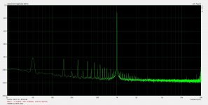
Luckily, I was able to team up with another inhabitant of diyaudio to build and test the thing. Like you, we also quickly found that a circuit that simulates well in Scilab and TINA may not be anywhere near stability on a physical circuit board. When we finally got the prototype stabilized, we needed a high precision signal source and a high quality signal analyzer to measure the remaining distortion and noise. We found a distortion spectrum that was almost purely second and third harmonic at levels around -126 dB when delivering 50 W at 1 kHz into an 8 ohm resistive load. The noise "grass" was around -140 dB and THD came out to 0.000071 %. This 100-watt prototype has 10x overall gain and a combined 75 dB NFB at 20 kHz (50 dB more than the basic chipamp on its own). It was built with a LM4780, a LME49740 (input buffer + driver stage) and surface mounted passive components to keep all signal paths as short as possible.
Then we got ambitious and decided to try the OPA1611/12. It is an unforgiving beast that could easily decide to oscillate even on its own in a unity gain buffer if given some parasitic capacitance. It definitively makes the stability analysis for a composite amp more interesting. I don't think I would try this without a good Scilab model of the transfer function. This is, quite literally, close to rocket science.
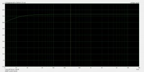
We now have a simulated version with sixth order compensation to deal with the kinked loop gain from the OPA1611 in addition to the decompensated LM3886. The higher order control loop also allowed us to do some noise shaping, similar to what Hypex does in the fourth order nCore loop, but we placed the loop gain maximum (and noise minimum) around 6 kHz instead of 13 kHz as in nCore. We again set the closed loop gain to 20 dB and the closed loop bandwidth (-3 dB) to 125 kHz.
The OPA1611/LM3886 circuit actually simulates quite well both in Scilab and TINA. It seems possible to add some more NFB across the audio band with this compensation scheme than in the first prototype. It also seems that the OPA1611 will give a useful noise reduction, so one challenge is to make the input buffer equally quiet. TINA simulation of the entire bridged amplifier including input stages shows total output noise around 6 uV with inputs shorted and 20 kHz measurement bandwidth. The next step will be to do the circuit board layout, build the thing, and get a whole new set of unpleasant surprises.
If and when it is working as intended, it probably deserves a thread of its own here. Until then, a big thank you for sharing your knowledge both here and on the Neurochrome site. Very inspiring, enough info to start looking in the right direction, but not so much that all the challenge is gone either. 🙂
Last edited:
BTW, I found that a useful way of thinking about the compensation schemes is in terms of bandwidths and speeds. The challenge is that the driver opamp is much faster than the power opamp, leading to a system that is difficult to control. The compensation scheme could be understood as slowing down the controlling stage while speeding up the controlled stage to make their bandwidths more-or-less similar. If you make the controller even slower, stability is easy, but you might wind up with a DC servo instead of a composite amplifier. 🙂
If you make the controller even slower, stability is easy, but you might wind up with a DC servo instead of a composite amplifier. 🙂
Dominant pole compensation always works... 😀
Tom
asbjbo- sounds like excellent work. Bruce Hofer said that the composite amp sections for the APX 555 were the most challenging project he ever confronted.
The usual gain for a power amp is 26 dB or the THX gain of around 29 dB. 20 dB is a little low. It also makes stability a little more difficult. The distortion figures are so low you could probably sacrifice a little with more gain and not lose anything important.
How much does the distortion degrade at higher frequencies? I would expect a faster increase than a single amp.
Thanks! Yes, dominant pole compensation works. We use an inverting driver stage as an integrator, shaping the gain plot there to emulate a slower opamp. The noise shaping and clipping behavior is also decided there. The tradeoff is to avoid throwing away too much NFB in the audio band while ensuring stability.
The 20 dB gain is a design choice. I will use these with high efficiency loudspeakers (~100 dB @ 1 W), so both low gain and low noise are important. Actually, we take most of the overall gain already in the balanced input buffer to improve noise performance. The composite amplifier itself runs at less than 10 dB gain. We can set overall gain by changing one resistor in the input buffer.
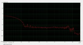
The high precision signal source we used is not sweepable, so I do not have a good plot of distortion vs frequency. But we saw distortion products around -120 dB in a 19+20 kHz IMD test with both frequencies at 15.8 V RMS. I suspect most of it came from the signal source used in the test. This thing has ~50 dB more NFB at 20 kHz than the datasheet LM3886 chipamp. For the next version, we are aiming at even better performance, but I am not sure we will be able to measure it. The simulated unweighted noise across the audio band is equivalent to the thermal noise of a 1.5k resistor followed by a noiseless 10x amplifier.
There is huge performance potential in the composite amplifier concept. A measurement with a regular sound card will probably not show much more than the distortion and noise in the sound card itself.
The 20 dB gain is a design choice. I will use these with high efficiency loudspeakers (~100 dB @ 1 W), so both low gain and low noise are important. Actually, we take most of the overall gain already in the balanced input buffer to improve noise performance. The composite amplifier itself runs at less than 10 dB gain. We can set overall gain by changing one resistor in the input buffer.
The high precision signal source we used is not sweepable, so I do not have a good plot of distortion vs frequency. But we saw distortion products around -120 dB in a 19+20 kHz IMD test with both frequencies at 15.8 V RMS. I suspect most of it came from the signal source used in the test. This thing has ~50 dB more NFB at 20 kHz than the datasheet LM3886 chipamp. For the next version, we are aiming at even better performance, but I am not sure we will be able to measure it. The simulated unweighted noise across the audio band is equivalent to the thermal noise of a 1.5k resistor followed by a noiseless 10x amplifier.
There is huge performance potential in the composite amplifier concept. A measurement with a regular sound card will probably not show much more than the distortion and noise in the sound card itself.
Last edited:
- Home
- Amplifiers
- Chip Amps
- Composite amplifier: LM3886 + LME49710