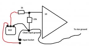
The potentiometer has three terminals. With the control turned anticlockwise (what will be minimum volume) the centre pin should read almost short circuit to one of the outer pins.
That outer pin is ground and must connect to ground. The centre pin is the wiper (the moving contact) and that goes to the input of the amplifier circuit (pin 10). I think your diagram shows a series 1k which is fine.
The other end pin of the control goes to the RCA input socket (centre pin of socket). This feeds the audio onto the control.
Also make sure the outer (ground) of the socket connects to ground in the amplifier.
The difference if you compare them is in how far you have to turn it (degrees of rotation) to get the same level of audio... the log pot matches our naturally logarithmic hearing and so as you turn the control you find the audio 'sounds' to increase fairly constantly as you rotate the control. In other words the log pot actually gives an apparent linear increase in perceived level as you turn it.
The linear control still gives exactly the same achievable levels but it feels all wrong in the actual level you hear vs how far you are turning the pot to get that level.
One problem with some log pots (often cheap carbon types) is that they can have poor tracking between the two gangs which means that at low levels one channel can change in level more than the other and so the stereo image shifts as you reduce the level right down.
You can fake a log law with the linear pot by the simple addition of one resistor between the middle pin of the pot and the ground pin of the pot. Linear pots often track better between the two channels. The value of the resistor depends on the value of the pot used.
And this is where I am now. I've soldered the four resistors onto the potentiometer and joined the connections from the RCA inputs to it. Do the two connections from pin 10 go here too? Or am I wrong?

Mine looks vaguely like that, yes! 🙂 So I might actually be able to connect some speakers etc and try it out (using the DBT obviously)? 🙂 The only thing I haven't wired up yet is the LED...
Last edited:
Before connecting speakers you should check that there is no DC present at the speaker terminals. The bulb should be dim.
Well, that was disappointing. Plugged it in, no light from the dim bulb tester, but the 220v switch lit up, the front switch was on too, but....nothing. Not a sausage. So. What can I test? 🙁
Last edited:
Fault finding always begins with measuring voltages. If the bulb didn't even flicker when you switched on then you may have the transformer wired incorrectly. The bulb should at least flash as power is applied.
So begin by measuring the AC voltage (make sure your meter is set to AC volts) coming out of the transformer.
If that is OK then measure the DC rail voltage across each of those big caps. In fact as that is the easiest do this step first.
So begin by measuring the AC voltage (make sure your meter is set to AC volts) coming out of the transformer.
If that is OK then measure the DC rail voltage across each of those big caps. In fact as that is the easiest do this step first.
I've checked all of the wiring and found one not properly soldered. Re-trying it, I get a dim light at the bulb for a short while, then crackling sound from the speakers. This is a crackle, not a hum and is quite loud. It doesn't change when the volume knob is turned.
We still never assume anything when faultfinding.
Are the two DC rails correct i.e. at their expected voltages (perhaps a little low because of the bulb) and also is the DC offset at the speaker terminals very close to zero volts DC.
Are the two DC rails correct i.e. at their expected voltages (perhaps a little low because of the bulb) and also is the DC offset at the speaker terminals very close to zero volts DC.
I am getting almost zero at the speaker terminals, but where exactly do I test the DC rails? At the + and - under the big caps? Sorry to be thick.
Zero at the speakers is good so that is a start. The DC rails are simply the voltages the amp uses to operate and these are always checked first with any faultfinding.
You measure from ground (which should be the centre connection between the two big caps) to each end of the caps in turn. One will be PLUS say 20 volts and the other NEGATIVE 20 volts.
Exact value depends on your transformer voltage. The bulb will also reduce the value somewhat.
You measure from ground (which should be the centre connection between the two big caps) to each end of the caps in turn. One will be PLUS say 20 volts and the other NEGATIVE 20 volts.
Exact value depends on your transformer voltage. The bulb will also reduce the value somewhat.
Right, there's 0.01v at the speakers, +28v and -28v at the caps. The dbt lights up briefly when I power up. No sound or crackling though.
10 mv offset is good and suggests the amp is basically 'working'.
Without a means of signal tracing this all becomes guess work...
Check with the amp OFF:
1/ That you do not have a short circuit across the RCA input sockets.
2/ That the centre pin of the RCA goes to one of the end pins of the volume control.
3/ That you have connectivity from the centre RCA pin to the wiper of the volume control if the volume control is on full.
4/ Continue the above check and confirm you have continuity from the RCA centre pin all the way through to pin 10 of the chip. Remember to account for any coupling caps as they will 'break' the DC continuity. Also account for any series resistance, for example the 1k connected in series with the audio in the diagram in post #9. (if OK remember to turn it back down).
5/ Check that the speaker terminals have continuity to ground for one of them and continuity to pin 3 for the other one.
6/ Have you correctly configured the mute pin (pin 8).
I've tested all of the things you've suggested, but I'll have another go at point 4 of your list. One thing I've found, is that I have continuity between pin 3 and both speaker terminals. Going by what you've said, this shouldn't be the case?

I have attached a schematic of a layout that I used for my first P2P GC. I found this logical enough for me to follow. Mooly, if this conflicts with the advice you have given or feel that it is unnecessary then fell free to delete it.
The layout is from the Decibel Dungeon website.
Last edited:
^ not at all 🙂
----------------------
Pin 3 of the chip should have continuity to only the plus speaker terminal of the relevant channel. The other terminal (the negative speaker terminal) should have continuity to ground.
Remember that your meter may appear to show continuity if used on an inappropriate range. What we are looking for is almost zero (0.00) ohms.
You must use a 'low ohms range' on the meter to get an accurate result. If you use a 'high ohms range' then you will read what seems like continuity between many different points.
I've mis-read the meter when looking at the speaker terminals: they're okay. What I don't understand is that after pin 8 is joined to pin 4, it just ends on the board. Pin 8 doesn't seem to connect to anything after this (?)
- Home
- Amplifiers
- Chip Amps
- Complete novice alert! *don't read if easily annoyed by stupid questions*