Okay, thank you. Now, back to my original question: What do I connect to the connectors that come from pin 10 and pin 1 please?
Yes, thank you I know that. I am referring to my original post and the photograph where I have said that I am stuck. I need to know where to physically connect from the connectors soldered to my board in the places that are ringed on the photo to where they should be connected to next.
I think we need a bit more info from yourself here 🙂 I can't see anything 'ringed' in the image on post #1. That is your actual amplifier is it? and not just a picture off the web.
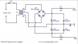
Lets begin with the power supply and transformer. Is that wired up correctly now to the rectifier and reservoir caps?
Lets begin with the power supply and transformer. Is that wired up correctly now to the rectifier and reservoir caps?
Sorry, I thought I posted this before...

This is as far as I've got and that's why I am stuck. The connections from pins 1 and 10 go to these two connectors. And then where? I can't seem to understand where they go from here.
This is as far as I've got and that's why I am stuck. The connections from pins 1 and 10 go to these two connectors. And then where? I can't seem to understand where they go from here.
It still all sounds a bit of a mystery tbh.
Pin 1 of the LM3886 and pin 5 of the chip should be joined and these then go to the positive rail which will be the plus end of one of those large caps.
So looking at your picture the + end of the cap furthest from us would be that point. I can't understand why you would have pin 1 coming out to a connector.
Pin 4 of the chip should go to the negative rail and that looks like it would be the negative pin of the cap nearest to us.
Pin 10 is the non inverting input of the chip and is where the audio is applied but it should not just be a connection direct to the pin. This input should be tied to ground (the 0V point) via a resistor, typically 22k.
PRR posted a diagram in post #7 which I think is from the site you linked to. The configuration of the chip should be as in that diagram. You can see pin 10 goes to a volume control in that image.
A good way to figure things out is to look at each pin of the chip in turn and confirm it goes where it should.
Okay I will have a close look at all of it and re-check what I’ve done. Thanks so much again for your help.
Working from pictures is never easy but if you get stuck then just ask 🙂
One thing I would say is that you must use a 'DBT' or dim bulb tester with this project. It could save you from expensive mistakes as you first power it all up. It's vital... and use a low wattage bulb if you can such as a 60 watt or lower (filament type only)
One thing I would say is that you must use a 'DBT' or dim bulb tester with this project. It could save you from expensive mistakes as you first power it all up. It's vital... and use a low wattage bulb if you can such as a 60 watt or lower (filament type only)
I am using a DBT at all times, don't worry 🙂 I haven't blown myself (or anything else) up yet. Working from pictures might be tricky, but it's all I'm good at (graphic designer). So here's another one...so that I can get my head around what is going on under the board, I drew this...

I hope you can see what I've done from this. I know it's not a schematic, but it's all I can do 🙂
I hope you can see what I've done from this. I know it's not a schematic, but it's all I can do 🙂
First comment... the LED (and I assume a series resistor to it) should be fed from the DC supply, not direct off the transformer. AC even when a series resistor is used will cause the LED's maximum reverse voltage to be exceeded. The LED will also visibly flicker.
So connect the LED and resistor across one or other of the large caps. The resistor needs to be around 10k or higher. It all depends how efficient the LED is and how bright you want it. Be sure to get the polarity correct.
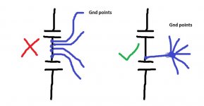
The blue connection joining the two caps becomes the 0 volt or ground point, however it is very important that you do not connect multiple individual wires to this connection but rather take a single spur off that wire, the end of which becomes the true ground reference point. It is all to do with high charging currents flowing in the blue wire and these will cause hum and buzzing if you just randomly connect to this.
So connect a single wire taken from any point along that common connection (it doesn't where or which end) and use the end point of the new spur as a common ground point.
I'll look at the rest a little later 🙂
So connect the LED and resistor across one or other of the large caps. The resistor needs to be around 10k or higher. It all depends how efficient the LED is and how bright you want it. Be sure to get the polarity correct.
The blue connection joining the two caps becomes the 0 volt or ground point, however it is very important that you do not connect multiple individual wires to this connection but rather take a single spur off that wire, the end of which becomes the true ground reference point. It is all to do with high charging currents flowing in the blue wire and these will cause hum and buzzing if you just randomly connect to this.
So connect a single wire taken from any point along that common connection (it doesn't where or which end) and use the end point of the new spur as a common ground point.
I'll look at the rest a little later 🙂
So you must check, check and check again 🙂 Go through each of these individually.
1/ Using your meter on ohms confirm that pin 1 and pin 5 are connected together.
2/ Check that these two pins connect back to the lower caps + terminal on your diagram (positive rail).
3/ Check that pin 4 of each chip connects back to the - terminal on the upper cap (negative rail).
4/ Pin 10 is the audio input. This has to be correctly terminated, it can not just be an open connection.
We need to know how you intend to use this amplifier. Are you wanting RCA inputs and having it as a power amp to use with an external preamp or are you wanting it to have its own volume control?
All this effects what we do with the connection to pin 10.
5/ Pin 7 should connect directly back to our ground reference point (the spur).
6/ Pin 9 should confirm to the configuration of the circuit you are working to. and connect via the feedback resistor to pin 3. There should also be a feedback return network of resistor and series cap and these go to the ground reference point.
7/ Pin 8 is the mute pin and should go to the negative rail via a series resistor. You show 10k which should be OK.
8/ Pin 3 is the audio output. There should be a series resistor and capacitor network (Zobel network) from pin 3 to ground. This is for stability. There should also ideally be a small series inductor from the wire from pin 3 to the speaker socket. That is for stability as well... you can try without it.
Is that all the pins covered 🙂
I've done as you suggested (hopefully) and this is how it looks now...

I still need to add a spur from the caps to ground. I have left pins 10 as they were for now.
I am using this as an amp with RCA connectors and it needs it's own volume control.
Pins 9 and 3 I don't quite get. At the moment there's nothing connected to them in the way of resistors AFTER the board. Do you mean there is supposed to be caps and resistors before it gets to the speakers?
Last edited:
Pin 9 should connect to the feedback network. This means pin 9 connects to pin 3 via a resistor, typically 20 or 22k in value. Pin 3 then also goes to another resistor and a cap wired in series (typically a 1k and 22 or 47uF cap) and the other end of this goes to ground.
Pin 3 is the output and this goes to the + speaker socket. Normally there is a series coil included as well which aids stability with adverse loads. If you haven't got the coils fitted then leave it be for now.
Pin 3 also connects via a series resistor and cap to ground. The data sheet shows 2.7 ohm and 0.1uF here.
Be sure you understand the spur principle.
Attachments
Okay, I'll add the suggested cap and resistor to pin 3. I have a spur of earth wires, but this is very crowded now. Could I just have one other small spur for the last couple of ground connections?
I'll answer that by saying that if you must then take another spur of the existing one. Don't add another to that common connection between the caps.
The whole object is to prevent the volt drop that occurs in that common connection from generating unwanted voltage between ground points in the amp. Although the voltages may seem miniscule it is these very voltages that are at the root of most hum and buzzing problems in amps.
The whole object is to prevent the volt drop that occurs in that common connection from generating unwanted voltage between ground points in the amp. Although the voltages may seem miniscule it is these very voltages that are at the root of most hum and buzzing problems in amps.
This is where I am now. I hope this makes sense to you..

I'm not sure what goes to the potentiometer, I assume it's input from the RCA plugs, but what else?
I'm not sure what goes to the potentiometer, I assume it's input from the RCA plugs, but what else?
The potentiometer has three terminals. With the control turned anticlockwise (what will be minimum volume) the centre pin should read almost short circuit to one of the outer pins.
That outer pin is ground and must connect to ground. The centre pin is the wiper (the moving contact) and that goes to the input of the amplifier circuit (pin 10). I think your diagram shows a series 1k which is fine.
The other end pin of the control goes to the RCA input socket (centre pin of socket). This feeds the audio onto the control.
Also make sure the outer (ground) of the socket connects to ground in the amplifier.
- Home
- Amplifiers
- Chip Amps
- Complete novice alert! *don't read if easily annoyed by stupid questions*