Toshiba IGBT's for sale....
HI!
I have some IGBT's for sale:
2 x GT20D201
2 x GT20D101
They are used in all the Elektor amps.
Price: 65 Euro for them all.
Mail if interested: mail@peterlund.org
- Peter
HI!
I have some IGBT's for sale:
2 x GT20D201
2 x GT20D101
They are used in all the Elektor amps.
Price: 65 Euro for them all.
Mail if interested: mail@peterlund.org
- Peter
IGBTs are tricky since they can be designed in various flavors
There are some IGBTs whose main features are very low conduction losses, low price and ease of drive, but at the expense of slow switching and large current tails.
These kind of devices are represent the clasical old concept of 'slow' IGBT designed to be used in LF high-current switching [10Khz or less] on industrial applications. You can even find 1.000A 1.200V devices with only 2V or so voltage drop when ON and much cheaper than similar MOSFETs
But there are also modern IGBTs designed for fast switching at the expense of having conduction losses only slighthy lower than MOSFETS, that claim to be fully ON in 50ns and fully OFF in 300ns or less [for 10A 400V switching and a 10A device : SKP10N60 from Infineon]
These devices represent a new concept of IGBT designed to replace MOSFETS in SMPS up to 150Khz with total losses equal or lower than equivalent MOSFETS, lower EMI and very ease of drive due to lower capacitances and no ringing, available in TO-220 packages and 3-5 times cheaper than similar 600V MOSFETS
Look for Infineon SGP and SKP series, International Rectifier has also similar stuff but Infineon appears to have equal or better specs at lower prices
I suppose the root of the problem is that those Thosiba GTD devices are slow old-fashioned ones, not to talk about their price is INSANE. Actually I see no point in using such devices since a pair or two of modern fast Toshiba bipolars will perform better and will be cheaper
I don't know if modern fast IGBTs are suitable for lineal amplifiers since I've never tried that and these devices are only available in 'n-channel' fashion, but In the practice, I've used them succesfully to switch 10-30A at 450V and 90Khz with voltage rise and fall times under 150nS [driving the gate hard appears to speed-up switching]
>Actually I see no point in using such devices since a pair or two >of modern fast Toshiba bipolars will perform better and will be >cheaper
What Toshiba bipolars would you suggest as substitute for the IGBT's?
- Peter
What Toshiba bipolars would you suggest as substitute for the IGBT's?
- Peter
I was thinking about 2SA1943 and 2SC5200 and similars [there are also good devices from Sanken]
But this output stage is designed to charge the gate of a IGBT or a MOS device, not to provide base current to a power bipolar transistor
When I mentioned bipolars I was obviously meaning that they aren´t suitable as a direct replacement for IGBTs without redesigning the circuit, but if I had to design an amplifier from scratch, I would use bipolars instead of IGBTs
There may be some mosfets usable as a direct replacement, but possible thermal runaway of bias current should be analyzed with care [I have no experience with mosfets in linear circuits]
Sorry to bring back an old thread, but...
http://www.tubecad.com/email_2001/e0829/e0829.pdf
janneman, can the approach of figure d) using samples of output current and voltage be used to make an amplifier have output power (V*I) proportional to input voltage? I've been trying to find information on such a power amplifier, but all I've found is a reference on page 4 in this tubecad journal letters:janneman said:Well Jorge and others, nice story about the feedback signal injected as a current in the input stage, except that this doesn't make it CF. Voltage feedback means you feed back a sample of the output VOLTAGE (as in this Elektor amp). CF is when you feed back a sample of the output CURRENT.
Look at these circuits:
Fig a shows output voltage from output stage fed back by R and C - BY DEFINITION voltage feedback, even if it goes to the cathode of the first stage (functionally equivalent to the elector buffer output stage emitters), which is a low impedance, so one could indeed argue that the feedback signal is injected into the input stage as current. The point is that the feedback signal is proportional to the output voltage, thus VF...
Fig b : the output current develops a voltage across Rf, that signal is send back: the feedback signal is proportional to the output current, this is BY DEFINITION CF, even if it is fed back to a voltage-input (hi impedance, the grid).
Fig c: Clearly voltage feedback.
Fig d: Both VF from the output signal, and CF from the output current. The unbypassed Rk develops a voltage from tube's current (Ia = Ik) this current gives a voltage across Rk which is put in series with input voltage Es, but in opposite phase (after all, it IS negative feedback).
Fig e: This is the quiz. VF or CF?
Jan Didden
http://www.tubecad.com/email_2001/e0829/e0829.pdf
I know you didn't ask me, but anyway: using a feedback signal that is the sum of a signal proportional to the output current and a signal proportional to the output voltage results in an output impedance that tends to some well-defined value when the loop gain tends to infinity. Using only one of these two types of feedback makes the output impedance tend to either zero or infinity.
Two-loop feedback is very useful when you want an output resistance that is neither zero nor infinite, but don't want to waste power in a series resistor in series with the output of a "normal" amplifier. (Of course you need a series feedback resistor that also dissipates power, but it can usually be much smaller than the realised output resistance.) Besides, you can make the output resistance negative when you use a combination of positive and negative feedback. This can, for example, be useful to increase the damping of a loudspeaker.
In any case, the product of output voltage and current does not become proportional to the input voltage.
By the way, if the product of output voltage and output current of an amplifier would be proportional to its input voltage, then the amplifier would be grossly non-linear. With a linear load, the output voltage would be proportional to the square root of the input voltage.
I can't think of any reason why anyone would want this, but if you really want it, you could try incorporating a translinear multiplier in the feedback loop that calculates the product of the output voltage and output current.
Anyway, feedback amplifiers with a linear combination of voltage-to-voltage and voltage-to-current feedback, without any form of multiplier, are sometimes confusingly called voltage-to-power amplifiers. This term is misleading, since they do not keep their output power constant when the load is changed.
MarcelvdG said:[snip]In any case, the product of output voltage and current does not become proportional to the input voltage.
I agree. If you want that, use a multiplier and feed it with a sample of the output voltage and a sample of the output current (picked off from a smallish series resistor) and use the result to drive the feedback loop. You will then have an amp that will regulate it's output voltage in such a way that the output power has a linear relation to the input voltage. But I don't know where this would be good for.
(Sorry, didn't read the whole thread).
Jan Didden
Sorry I wasn't explicit, I'm driving plasma where delta-input-electrical-power is delta-pressure, so translates directly to acoustic power.But I don't know where this would be good for.
Now I must ask a stupid question: how do you make the kind of multiplier you mentioned?
Dear Prune,
You need a one- or two-quadrant analogue multiplier. These are usually made with translinear circuits. In general, this is not a trivial subject; complete textbooks and many PhD theses have been written about the design of translinear circuits. Analog Devices used to be specialised in high-performance translinear ICs.
Fortunately, a one-quadrant analogue multiplier is one of the simplest translinear circuits, as long as you have no extreme accuracy requirements. If both the output current and the output voltage have a DC component greater than the peak AC value, their direction is always the same, and you can use a one-quadrant multiplier.
All (bipolar) translinear circuits are based on the fact that the collector current of a bipolar transistor depends exponentially on its base-emitter voltage. (This is true when it is biased in the normal, forward active region (not in saturation) and not at extremely high or low current densities.) So the base-emitter voltage depends logarithmically on the collector current. You can use this to change a multiplication into an addition of logarithms.
The signals you want to multiply have to be converted into currents. Let us call them I1 and I2. Then you have to make I1 flow through one transistor, I2 through a second transistor and add the base-emitter voltages. After subtracting a base-emitter voltage of a transistor biased at a constant reference current, the remaining voltage can be put between the base and emitter of a fourth transistor. The collector current of the fourth transistor then equals I1*I2/Iref. This only works properly with well-matched transistors having equal temperatures.
I have no schematic editor here, so see the netlist:
Syntax:
Transistors:
Qsomething C B E type
Voltage sources:
Vsomething + -
Current sources:
Isomething node1 node2
with the current flowing from node1 to node 2.
Q1 1 2 0 NPN
Q2 3 1 2 NPN
I1 3 1 {I1}
I2 2 0 {I2}
Qref 3 1 4 NPN
Iref 4 0 {Iref}
Qout 5 4 0 NPN
VCC 3 0 {VCC}
Vload 5 0 {Vload}
where Vload should be >0.3V to prevent deep saturation and VCC should be at least 1.5V...2V.
Like this?
Is performance good enough for audio, for multiplying negative feedback signals?
An externally hosted image should be here but it was not working when we last tested it.
Is performance good enough for audio, for multiplying negative feedback signals?
In theory, such a multiplier can be extremely accurate with ideal bipolar transistors having no bulk resistances, no high-injection effects, infinite current gain and no Early effect. In practice, the performance is limited by all these second-order effects.
The performance therefore depends on the quality of the transistors. It is best to use a transistor array with high current gain and low bulk resistances, such as a MAT04, and experiment (either in real life or in a simulator) with what current levels give the most acceptable performance. Too low currents result in a bad signal-to-noise ratio, too high currents in a high distortion. It is advisable to keep the collector voltage of the output transistor constant to avoid additional distortion due to Early effect.
In any case, translinear circuits are often used in controlled amplifiers in DC controlled analogue mixing consoles.
Elektots' Compact Audio Amplifier
Just because there is a resistive divider between the output of the amplifier and its inverting input doesn’t make it a voltage feedback system. In fact, if we are referring to an ideal CF amp, there cannot be a voltage at the output of the divider since the input impedance of the CF amp at the inverting input is zero. Only the error current can flow, driving the non-inverting input current to zero.
CF amps can have distinct advantages over voltage feedback types. Doug Smith, et al, in ‘Evolution of High-Speed Operational Amplifier Architectures”, IEEE JSSC, Vol. 29, 1994, explain how the absence of first-order slew limiting in a CF amp can yield very high slew rates. Third-order distortion is also superior in CF amps.
For these reasons I built Elektor’s Compact Audio Amp four years ago and I can tell you that I have not regretted it. It regularly beats classic commercial amplifiers of comparable cost like the Audiolab 8000A hands down. It does require some tweaking though.
This elector's amp is a good design as far as the specifications are concerned as well as the theory behind this design. However IMHO its sound capability and the spectral content of this amplifier, at least to my ears, is not alot better than most mid priced commercial offerings.
P.S Hollow man, please contact me on panos29@yahoo.com
P.S Hollow man, please contact me on panos29@yahoo.com
I think that it is a current amplifier
😀
adding fuel to the fire.. hehe, just kidding, look up transconductance amplifers and schematics these are true current feed back if you want to settle the argument.
I have not built this elektor amp but it looks quite symetrical good idea in theory,
however if it is as touchy as everyone says it is then it is possibly a good idea to include some resistance on each of the output devices collectors, say 4 ohms on each collector during testing and with no load. and then check all the voltages are correct, this should not affect in any way the voltage testpoint readings. and will make it impossible(well almost impossible) to blow up the output devices.
Just wanted to say that this amp, after a few mods, can trully sing - and never mind the theories...
hollow_man said:Just wanted to say that this amp, after a few mods, can trully sing - and never mind the theories...
Hollow man, please can you be a bit more specific about which modifications you made? Maybe you remember some suggestions made by Peter Jacobi in this thread , january 2004. Did you perform mods like his proposals, ore...?
Improving the thing
I will post the modifications I have done, but because they are quite a few, I will not go into detail or the reasoning behind them. Please note that I have sonically verified all of them.
OK, so here goes:
- Remove T8. Lift Gate and Source of T7 and return them shorted, via a 6K8 resistor, to the base of T4 (there is no connection to ground).
- Remove C3 and C4.
- I use a passive preamp so I have made C2 150p and shorted C1.
- R5=560R, R6=560R in series with a small resistor to equalise T3&T4 collector currents.
- Use a small breadboard design to successively match T1 to T2 and then T5 to T6. This will have the current sources and the associated components around the transistors to be matched. You can then reduce the DC servo loop gain by making R42=27K.
- Remove phase-lead networks R12/C8 and R15/C10 and replace by a short.
- Remove C12 and C13.
- C14=47n MMK
- Cut pcb tracks between R19/R20 and R22/R23 and insert ferrite beads.
- Remove R28 and C17. Insert 20K resistors from the collectors of T12 and T13 to ground.
- C15=C16=330uF/25V audio grade.
- R32=R36=150R.
- Use dual bridge rectifiers at the power supply lines, one for each polarity.
- Omit the on-board power-on delay circuitry and short the relay. Use a crowbar DC protection circuit (details are available).
- I avoid turn-on noises by a mains soft-start circuit.
Note that the phase margin is actually increased a bit.
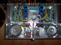
I am attaching a picture too.
Hollow_man
I will post the modifications I have done, but because they are quite a few, I will not go into detail or the reasoning behind them. Please note that I have sonically verified all of them.
OK, so here goes:
- Remove T8. Lift Gate and Source of T7 and return them shorted, via a 6K8 resistor, to the base of T4 (there is no connection to ground).
- Remove C3 and C4.
- I use a passive preamp so I have made C2 150p and shorted C1.
- R5=560R, R6=560R in series with a small resistor to equalise T3&T4 collector currents.
- Use a small breadboard design to successively match T1 to T2 and then T5 to T6. This will have the current sources and the associated components around the transistors to be matched. You can then reduce the DC servo loop gain by making R42=27K.
- Remove phase-lead networks R12/C8 and R15/C10 and replace by a short.
- Remove C12 and C13.
- C14=47n MMK
- Cut pcb tracks between R19/R20 and R22/R23 and insert ferrite beads.
- Remove R28 and C17. Insert 20K resistors from the collectors of T12 and T13 to ground.
- C15=C16=330uF/25V audio grade.
- R32=R36=150R.
- Use dual bridge rectifiers at the power supply lines, one for each polarity.
- Omit the on-board power-on delay circuitry and short the relay. Use a crowbar DC protection circuit (details are available).
- I avoid turn-on noises by a mains soft-start circuit.
Note that the phase margin is actually increased a bit.
I am attaching a picture too.
Hollow_man
Attachments
For anyone still playing about with this design, here is another worthwhile improvement:
The resistors from the collectors of T12 and T13 to ground are reduced to 2K2 each, so that the feedback is reduced to 24dB (from 42dB in the original design).
This makes for a very natural, effortlessly reproduced sound with a huge soundstage. Genuine hi-end material.
The resistors from the collectors of T12 and T13 to ground are reduced to 2K2 each, so that the feedback is reduced to 24dB (from 42dB in the original design).
This makes for a very natural, effortlessly reproduced sound with a huge soundstage. Genuine hi-end material.
Hi all,
I have build this amplifier 4-times in the original elektor design.
No problems, although the Bias adjustment was tricky, I had to use a 10-turn potentiometer instead of the simple open one forseen by Elektor.
The sound is suberb ! Very clear and detailed.
RolMar
I have build this amplifier 4-times in the original elektor design.
No problems, although the Bias adjustment was tricky, I had to use a 10-turn potentiometer instead of the simple open one forseen by Elektor.
The sound is suberb ! Very clear and detailed.
RolMar
- Status
- Not open for further replies.
- Home
- Amplifiers
- Solid State
- Compact Power Amplifier from Elektor