Here a couple of examples
https://ampslab-spk.com/2021/04/02/w20rc38-review/
https://ampslab-spk.com/2020/03/11/toucan-sf/
https://ampslab-spk.com/2021/04/02/w20rc38-review/
https://ampslab-spk.com/2020/03/11/toucan-sf/

There are electric ones, even battery powered and they are not that expensive.I don't own a nail gun and I don't have an air compressor in my shop.
Keep an eye on the max size nail they can shoot.
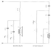
He actually only tested the 6" version W17RC38, but it has very similar characteristics as the W20RC38. Oddly the breakup peak on both versions is roughly at 4.5k which I find odd, but it correlates with my findings. I dont think $45 for a cast frame Chinese driver is premium in price, but I guess some stamped frame drivers can approach same quality levels. Its mainly the cast frame Im focusing on here.When did Zaph measure a 8" Silver Flute? That model has been off my radar...
US$45 for a Chinese made driver is a premium product.... please share measurements!
Sharing measurements is tough at the moment because my windows 10 laptop wants to force a windows 11 update when its on wifi, so i have to keep it offline. That makes it much harder to transfer files for me. I'm working on a fix for this. I can find some Clio measurements in the mean time from my screen shares.
You can get cordless brad nail guns at most hardware stores. They're just limited to the skinny trim nails typically used on base board mouldings.There are electric ones, even battery powered and they are not that expensive.
Keep an eye on the max size nail they can shoot.
The woofer loads the baffle with an out of plane load. The baffle is only slightly larger than the woofer hole, and the baffle is 1.5 inch thick, so most of the load will go into the side walls, either by direct loading at the juncture of baffle to sidewall, or by loading the the lower panel of the midrange enclosure, which in turn shears much of that load into the side walls. The horizontal "U" shaped brace behind the woofer restrains the side walls and keeps them from deflecting out of plane..
In general, my goal with the bracing was that no point on the cabinet exterior was more than 3 inches from an orthogonal wall or brace.


In general, my goal with the bracing was that no point on the cabinet exterior was more than 3 inches from an orthogonal wall or brace.
I guess you thought this through and it's okey, but somehow the braces feel "short." Front baffle gets support from base plate only by glue, I would add a brace that touches front, back and bottom. I would make the inside braces meet and glue in between, behind the woofer.
Enclosures designs with very narrow baffles are a challenge to get neutral midrange from. This is due to the inside cab side walls being too close to the woofer cone edges. The required amount of dampening to keep mids from reflecting into the cone back surface is hard to obtain with the lack of space. The higher mids aren't so much the issue, being easier to absorb with thinner materials. Its the 500 - 1000 hz range needing more attention and absorption material thickness. Luckily the OP design being a 3 way with the woofer not playing that high avoids a greater portion of mids radiating back compared to a 2 way design.
I usually prefer a U-shaped dampening baffle behind the mid instead of relying only on enclosure wall dampening. Aside from cleaning up the rear washed mids, it also effectively breaks up the resonance modes on the width and depth planes. This helps with ported enclosures to avoid most of port resonances from being excited.
I usually prefer a U-shaped dampening baffle behind the mid instead of relying only on enclosure wall dampening. Aside from cleaning up the rear washed mids, it also effectively breaks up the resonance modes on the width and depth planes. This helps with ported enclosures to avoid most of port resonances from being excited.
Have you got a picture or a sketch? I can't imagine what you mean from the description.I usually prefer a U-shaped dampening baffle behind the mid instead of relying only on enclosure wall dampening.

It also helps having a much higher flow resistance towards the port, dropping the ports Q factor significantly.This helps with ported enclosures to avoid most of port resonances from being excited.
Making the port a lot less effective.
Doesn't hemisperical subenclosure have a very strong 1st mode of standing waves. Does that happen in the passband?
Thats true, but I'd rather have a less resonant port than a more efficient one. I'd always want to do whats better for cleaner mids than settle for mid band coloration and a bit lower cutoff. Thats why I usually prefer sealed or TL enclosures for anything with an LF driver playing up into the midrange.It also helps having a much higher flow resistance towards the port, dropping the ports Q factor significantly.
Making the port a lot less effective.
Positioning the port for line of sight to the LF driver helps with losses, but it may create a less than ideal alignment with other unexpected side effects and anomalies having the enclosure baffled as in the drawing I posted. I've found its typically not an issue if you strike a compromise by using a minimum amount of dampening material and avoid blocking line of sight between the port and LF driver.
If someone can present a solution which avoids most box and port resonances in a small ported enclosure while not overly affecting alignment loss, I'd be all ears.
In the decades I've been building compact ported 2 ways, there wasn't anything you could do to avoid any amount of port resonances from being excited while keeping box losses to a minimum. It was a tradeoff you had to accept and it never works in favor of the midrange purity. I'd rather use separate subs and opt for a sealed design than deal with port resonances.
With smaller ported cabs, it makes more sense to use a PR since most alignments which play reasonably low require a port physically too long to fit. The PR avoids most problems here, although not as efficient. You still have the phase shift and.group delay issues, but for a design used mainly for casual listening, it may not matter so much.
There's definitely a dark art to building small ported 2 ways which don't suffer from intolerable amounts of port coloration. This and for other obvious reasons is why a snaller 3 way makes much more sense.
If the port isn't doing much anymore, you might just go for a closed box instead.Thats true, but I'd rather have a less resonant port than a more efficient one.
I have seen and measured plenty of designs where that was the case.
Point is, it's not that easy and black and white.
Fact is that a port in a 2-way system is always a compromise by definition.
Not so much with a 3-way system.
Since we are talking about a 3-way system here, I don't follow the purpose in this discussion?
Most of the time you cross somewhere around 200-500hz or so anyway.
Well below the first port resonance mode.
Below that mode the whole system works in the piston region anyway, so there is nothing to worry about.
@hifijim,
Be careful that you don’t set up a resonant system with two volumes V1 and V2 connected by a duct of length L and height D. There is a natural resonance here - it could easily be calculated with Akabak. Best way to alleviate is to use a lot of stuffing in the chambers and in the slot channel.

It would have been best to not make the mid chamber go the full width of the cabinet.
Be careful that you don’t set up a resonant system with two volumes V1 and V2 connected by a duct of length L and height D. There is a natural resonance here - it could easily be calculated with Akabak. Best way to alleviate is to use a lot of stuffing in the chambers and in the slot channel.
It would have been best to not make the mid chamber go the full width of the cabinet.
The bracing strategy has a couple of goals
The woofer is reacted above by the midrange subenclosure. Below it is reacted by the cabinet floor (bottom). On the sides it is reacted by the sidewalls. The baffle around the woofer will be 1.5 inch thick, and the beamwise span will be 2 inches or less, so the baffle will act less as a beam and more as a block. In other words, the baffle will have low deflection
The midrange is reacted above and below by the subenclosure. On the sides, the baffle has a short beamwise span to react the load to the sidewalls and to the upper and lower subenclosure walls. This is an area where I have potentially compromised performance in the interest of simplifying cabinet construction.
In the interests of managing tolerance buildup, I left a small gap between the vertical brace and the midrange enclosure rear wall. This gap will be spanned by a gusset block. Similarly there is a small gap between the horizontal woofer brace and the vertical brace, which is also spanned by a small gusset block.
If this project was about all-out performance, I would employ additional bracing. I would also double the butyl rubber damping layers.


"80 bil" should be 80 mil.... early morning fingers don't like to type...
- React driver loads into shear and axial loads within the cabinet walls. Minimize cabinet wall bending load paths
- Use a small number of braces
- Design the bracing to be insensitive to tolerance buildup, which means avoiding a large number of parts coming together in a precise way.
The woofer is reacted above by the midrange subenclosure. Below it is reacted by the cabinet floor (bottom). On the sides it is reacted by the sidewalls. The baffle around the woofer will be 1.5 inch thick, and the beamwise span will be 2 inches or less, so the baffle will act less as a beam and more as a block. In other words, the baffle will have low deflection
The midrange is reacted above and below by the subenclosure. On the sides, the baffle has a short beamwise span to react the load to the sidewalls and to the upper and lower subenclosure walls. This is an area where I have potentially compromised performance in the interest of simplifying cabinet construction.
In the interests of managing tolerance buildup, I left a small gap between the vertical brace and the midrange enclosure rear wall. This gap will be spanned by a gusset block. Similarly there is a small gap between the horizontal woofer brace and the vertical brace, which is also spanned by a small gusset block.
If this project was about all-out performance, I would employ additional bracing. I would also double the butyl rubber damping layers.
"80 bil" should be 80 mil.... early morning fingers don't like to type...
I will keep that in mind when I get to the measurement phase, so if I see something strange, I might guess the cause. It is too late to do much about it now, this design is almost completely built. I do plan to stuff the entire box with long fiber wool.Be careful that you don’t set up a resonant system with two volumes V1 and V2 connected by a duct of length L and height D.
- Home
- Loudspeakers
- Multi-Way
- Compact, low cost, active 3-way speaker