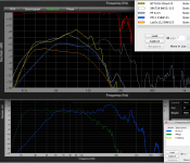
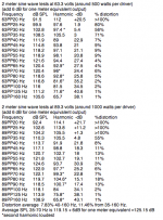
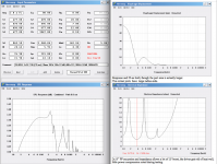
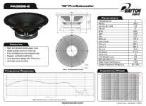
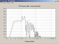
The 15" Dayton PA385-8 driver makes a very compact bass reflex cabinet with very high output and relatively low cost possible. Although this cabinet is considerably undersized, reducing potential low frequency output, the high power handling and relatively high Xmax make for good output down to 30 Hz, with actual measured output at 60 Hz over 130 dB at one meter, comparing favorably with commercial cabinets rated at 140 dB peak output. With EQ, a very wide range of 30 to 200 Hz is quite usable, the LF boost required to flatten response is done at frequencies where the speaker excursion is normally at minimum. The EQ used for the "PPEQ2" chart below was a DBX DriveRackPa set with 24BW filters at 30 & 100 Hz, PEQ +9 at 31.5Hz with a Q of 2.63, -12 at 67 Hz with a Q of 1.57.
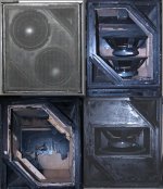
Having a pair of empty 26.5" x 22.5" x 22.5" cabinets available, but wanting more upper bass than previous Lab 12" speakers they were designed are capable of, the Dayton PA385-8 looked like a good choice, a Hornresp simulation showed as much 40 Hz output and almost 9 dB more 100 Hz SPL. Fitting 2 x 15" on a baffle that just barely fit 2 x 12" required using a slot (plenum) to fit. However, my first simulation was based on an overestimate of the actual interior net volume, which is only about 77 liters net, after accounting for the ports, handle area and push-pull plenum reductions. After test results showed less low frequency than expected, re-figured the cabinet volume and adjusted the Hornresp inputs, the resulting simulation match the LF response closely. The response of the upper end differs a bit from the simulation, the upper peak is lower in frequency and level. To achieve the 39 Hz Fb with the smaller cabinet volume required installation of a 5.75" long 3/4" thick plate with a 22.5" angle each end into the existing triangular corner ports. A 1.875" plate was added to the rear port entrance for more symmetrical port operation, the plates also brace the rear of the plenum.
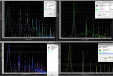
Originally I had planned to test the cabinet both as push-pull and push-push, but physical size restrictions only allowed the push-pull arrangement. The driver with the exposed magnet structure is connected reverse polarity, both drivers provide positive pressure with a positive signal. Push-pull orientation cancels much even order harmonic distortion, which for the Dayton PA385-8 is probably a good thing, as distortion still came in higher than any of the pro PA drivers I have tested, the push-pull pair showing over six times the average distortion of a B&C18SW115-4 at similar LF output levels. The Dayton PA385-8 forward and rearward excursion offset (cone position forward or rearward from at rest position) was quite visible during testing at various frequencies, the cone position can be quite inconsistent with single tones, though with pink noise or music it was not so apparent.
The PA385-8 has very little power compression, the venting design gets rid of the voice coil heat very effectively with very little noise, though plenty of lingering adhesive curing stink was evident during (and after) each high power outdoor test. There seems to be more port and slot compression than power compression, the response falls off slightly at both ends of the passband, while almost linear midband at the maximum pink noise output available from the SpeakerPower SP4001 used for testing. The magnet structure only rose a few degrees over ambient temperature in any of the tests.
On a cost per output ratio, the Dayton PA385-8 scores really well, though if low distortion is a high priority, this driver does not fare well compared to more costly alternatives, as can be seen in the examples below.
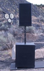
These small cabinets won't win any sensitivity awards, but given around 1000 watts per driver, the output is quite good, the walls of my shop made flapping noises during the tests from 22 meters away. At about 115 pounds, they are not lightweight, but the weight makes for a very stable base for pole mounted top cabinets. Loads of kick for the size, and upper response that can go high enough so pint-size top cabinets can be used and still have plenty of low mid "grunt".
Art
Having a pair of empty 26.5" x 22.5" x 22.5" cabinets available, but wanting more upper bass than previous Lab 12" speakers they were designed are capable of, the Dayton PA385-8 looked like a good choice, a Hornresp simulation showed as much 40 Hz output and almost 9 dB more 100 Hz SPL. Fitting 2 x 15" on a baffle that just barely fit 2 x 12" required using a slot (plenum) to fit. However, my first simulation was based on an overestimate of the actual interior net volume, which is only about 77 liters net, after accounting for the ports, handle area and push-pull plenum reductions. After test results showed less low frequency than expected, re-figured the cabinet volume and adjusted the Hornresp inputs, the resulting simulation match the LF response closely. The response of the upper end differs a bit from the simulation, the upper peak is lower in frequency and level. To achieve the 39 Hz Fb with the smaller cabinet volume required installation of a 5.75" long 3/4" thick plate with a 22.5" angle each end into the existing triangular corner ports. A 1.875" plate was added to the rear port entrance for more symmetrical port operation, the plates also brace the rear of the plenum.
Originally I had planned to test the cabinet both as push-pull and push-push, but physical size restrictions only allowed the push-pull arrangement. The driver with the exposed magnet structure is connected reverse polarity, both drivers provide positive pressure with a positive signal. Push-pull orientation cancels much even order harmonic distortion, which for the Dayton PA385-8 is probably a good thing, as distortion still came in higher than any of the pro PA drivers I have tested, the push-pull pair showing over six times the average distortion of a B&C18SW115-4 at similar LF output levels. The Dayton PA385-8 forward and rearward excursion offset (cone position forward or rearward from at rest position) was quite visible during testing at various frequencies, the cone position can be quite inconsistent with single tones, though with pink noise or music it was not so apparent.
The PA385-8 has very little power compression, the venting design gets rid of the voice coil heat very effectively with very little noise, though plenty of lingering adhesive curing stink was evident during (and after) each high power outdoor test. There seems to be more port and slot compression than power compression, the response falls off slightly at both ends of the passband, while almost linear midband at the maximum pink noise output available from the SpeakerPower SP4001 used for testing. The magnet structure only rose a few degrees over ambient temperature in any of the tests.
On a cost per output ratio, the Dayton PA385-8 scores really well, though if low distortion is a high priority, this driver does not fare well compared to more costly alternatives, as can be seen in the examples below.
These small cabinets won't win any sensitivity awards, but given around 1000 watts per driver, the output is quite good, the walls of my shop made flapping noises during the tests from 22 meters away. At about 115 pounds, they are not lightweight, but the weight makes for a very stable base for pole mounted top cabinets. Loads of kick for the size, and upper response that can go high enough so pint-size top cabinets can be used and still have plenty of low mid "grunt".
Art
Attachments
Last edited:
Chris,It looks like you're boosting around Fb. Any worries about burning the drivers with high power and minimal excursion?
Dayton claims "RMS Power Handling (w) 1,000" for the PA385S-8, which if correct may be equivalent to an A.E.S. rating of 1200 to 2000 watts depending on the frequency the power is applied at.
As I don't generally play sine waves centered at 39 Hz (the Fb, excursion and impedance minima) the cone will generally have plenty of movement at high power to pump hot air away from the voice coil, and the power amp I am using with the drivers is only capable of a little more than 1000 watts per driver. For heavily compressed program material with sine wave like content, limiting RMS voltage to around 75-80V would be prudent.
As a comparison, when running sine waves of equivalent of 400 watts to the Eminence Lab 12 (rated at 400 watts AES), the magnet structure would be hot to the touch after a suite of tests. The same tests using around 1700 watts in to the B&C 18SW115-4 (rated at 1700 watts AES) resulted in a slight warming.
The same tests using around 1100 watts in to the PA385S-8 (rated at 1000 watts AES) resulted in little warming of the magnet structure, and minimal power compression, a confirmation that the voice coil temperature is not extremely hot.
That said, enough heat is generated to make the adhesives used stink far more than I have noticed in testing any other speakers, hoping that the curing process is finished before the drivers are used at high power indoors.
Art
Attachments
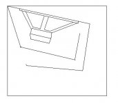
Whilst this is using an existing cab you've modified, have you considered some sort of single 15 horn reflex? You'd have a larger chamber that you'd tune to 40 or 50Hz and then a horn round the back with a ported access panel on the front.
Whilst I haven't looked into this at all, you may be able to get similar response using far less power and only one driver.
Also have you tried the cab with only 1 15 and blocking the other hole? I'd expect more lower bass and less upper bass.
Whilst I haven't looked into this at all, you may be able to get similar response using far less power and only one driver.
Also have you tried the cab with only 1 15 and blocking the other hole? I'd expect more lower bass and less upper bass.
Attachments
Last edited:
1) Been there, done that, the cabinet originally was a single 15" 30" deep "C horn". Your horn depicts a TH variant, I modeled similar, far less upper response (not desirable), similar lower response but much sharper cut off, also not desirable. Also, the drivers have rather high distortion already, though a single TH would increase level compared to a single BR, the distortion would almost double, too much for my taste.1)Whilst this is using an existing cab you've modified, have you considered some sort of single 15 horn reflex? Whilst I haven't looked into this at all, you may be able to get similar response using far less power and only one driver.
2)Also have you tried the cab with only 1 15 and blocking the other hole? I'd expect more lower bass and less upper bass.
2)Yes, modeled and tried it. Using a single 15" without the plenum would result in similar LF at Fb (due to the larger box size) but a lot less output above, where doubling the cone area and power results in +6 dB more output.
The SpeakerPower SP4001 amp I'm using is optimized for 2 ohms, I am running a pair of the ShoeHorns. Had the drivers been available in 4 ohms, I may have gone with a single driver per cabinet, though then they would have been running out of Xmax at the power available, and distortion would go through the roof, with less output than presently available.
As it is, the output is almost the same as a B&C18SW115-4 in a larger BR, at much lower cost, though heavier and more distortion.
There's always something...
") .
.With EQ, a very wide range of 30 to 200 Hz is quite usable, the LF boost required to flatten response is done at frequencies where the speaker excursion is normally at minimum.
Hmmmm, very interesting. I just realized there was a hole in my knowledge regarding your above comment. You have really opened my eyes to something important there. Thank you Sir.
I am not that familiar with the PPSL design and it benefits, but I spent a few minutes this morning researching it a bit. The lower distortion provided would seem to be a benefit, and also the compact size. Is there anything else that led you to choose this type of design?
Do you consider this PPSL design the highest and best use of the Dayton PA385? If you were to build it from scratch, would it be worthwhile to build it a little bigger to have better low frequency extension right off the bat, or as long as you were willing to EQ it, it wouldn't really matter?
1) PPSL reduces even order (the good sounding) distortion, but the plenum space reduces net volume, reducing LF for a given external box size, while increasing the upper response, and providing an acoustical bandpass, which reduces distortion of all types, though for sub use the distortion harmonics are lower than the BP. What led me to a PPSL loading a pair of 15" was it appeared to offer the maximum output in the frequency range desired for the existing cabinet dimensions and power available, and provided a lower (and near central front to back) center of gravity, essential for using the box as a safe pole base for top cabinets. PP also eliminates most cabinet "walking" typical of non-opposed loading. Since it turns out the Dayton PA385 has much higher distortion than any LF drivers I have used, PPSL was a good choice for them. As it stood, PPSL was the only way to fit 2 x 15" in the cabinet shape used.1)I am not that familiar with the PPSL design and it benefits, but I spent a few minutes this morning researching it a bit. The lower distortion provided would seem to be a benefit, and also the compact size. Is there anything else that led you to choose this type of design?
2)Do you consider this PPSL design the highest and best use of the Dayton PA385?
3)If you were to build it from scratch, would it be worthwhile to build it a little bigger to have better low frequency extension right off the bat, or as long as you were willing to EQ it, it wouldn't really matter?
Cone sag is a concern for horizontally loaded PP drivers, but the cabinets are stored with the drivers vertical, and for better or for worse, they will spend most of their time stored.
2) Define "highest and best" in some quantifiable manner, and I can answer accordingly.
3) Bigger would definitely be better as far as LF output, and the lower drive levels required to reach Xmax would generate less distortion, all good things. But bigger would not have met my size goal of cabinets no bigger than the small empty ones I had available.
Art
Last edited:
2) Define "highest and best" in some quantifiable manner, and I can answer accordingly.
Thanks for your response, Art. You have already justified why you chose the PPSL design given you were repurposing an existing cab. I was speaking more overall.
For us, what ever subwoofer we end up building, it will see a variety of uses by different family members. So for us, the "highest and best use" would be a compromise of size/weight/frequency response/SPL that would give us the best overall compromise for everybody.
Smaller/lighter/portable is always preferred, but if we can gain substantial SPL boost with a larger cabinet size, then that is always a possibility. Ideally we would like solid response from 40 Hz to 125 Hz. The only time we would really need super high SPL would be for an outdoor event - only once or twice a year. I have four of the Dayton PA-385's already, and the amplifier power to run them at their maximum.
Art, you have a lot of experience with folded horns/tapped horns/PPSL/ported BR boxes. If you were building something from scratch with this Dayton PA385 driver, what design would you be leaning towards? Thanks.
Hi DHAA,
I know you were asking Art, but
Post #9: "...what design would you be leaning towards?..."
(At the moment I'm not leaning anywhere as I still have a few plastic lines hanging of my body, but at least the cancer should be gone with the prostate.)
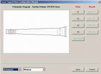
I'd work out a fold, and get out some inexpensive wood, and try to build this TH:
I know you were asking Art, but
Post #9: "...what design would you be leaning towards?..."
(At the moment I'm not leaning anywhere as I still have a few plastic lines hanging of my body, but at least the cancer should be gone with the prostate.)
I'd work out a fold, and get out some inexpensive wood, and try to build this TH:
Attachments
The best overall compromise for everybody leaves everybody mildly disgruntled most of the timeSo for us, the "highest and best use" would be a compromise of size/weight/frequency response/SPL that would give us the best overall compromise for everybody.
Ideally we would like solid response from 40 Hz to 125 Hz.
If you were building something from scratch with this Dayton PA385 driver, what design would you be leaning towards?
.Knowing now how much distortion this driver produces, I would not be inclined to load it harder than the present build, leaving out FLH and TH designs, and would definitely still employ push pull slot loading.
For "solid" (meaning -3dB at 40 Hz) response an increased net volume from 77L to around 180L with a 36 Hz Fb would increase output at 40 Hz and below by about 3 dB, reaching X max at 68 volts instead of 80. If you don't care about distortion, you could reduce gross cabinet volume dispensing with the PP plenum, but with a larger cabinet volume the plenum volume becomes relatively smaller, and a good portion of it is taken up with the volume of one of the drivers that otherwise would be displacing chamber volume.
If floor space in the clubs you might work in is as limited as it is here, my suggestion would be to use a 22.5 x 22.5 base dimension, make the vertical plenum offset to one side at the bottom of the cabinet so weight distribution is still centered (and the cones won't sag), use a large venturi shaped slot port on the opposite side, and increase the vertical cabinet height by the appropriate dimension to allow for the net volume increase.
Art
(At the moment I'm not leaning anywhere as I still have a few plastic lines hanging of my body, but at least the cancer should be gone with the prostate.)
I'd work out a fold, and get out some inexpensive wood, and try to build this TH:
Oh, my friend Oliver, I know about prostrate problems myself. I am sorry to hear about your problems, I hope you are feeling better soon and you get a clean bill of health. My wife prays for about everything imaginable, so I will have her add you to her list. Maybe you could sit on one of your subwoofers, crank it up, and give yourself a little massage back there.
Thanks for taking the time to come up with the tapped horn design in HR. Very nice looking frequency response, with some serious low-end! I will have to play around with that myself. I see you had S1 larger than S2, which is untypical. I had also used approach in some of my HR designs. Is there a particular T/S factor of the Dayton PA385 that makes that necessary? Thanks.
Hi Art,
Thanks.
A while back I played around a lot w/ cone correction (making up for the added volume/cross-sectional area the cone introduces into the horn path), and I often ended up w/ a larger S1. Some drivers like it some don't, just don't know the reason why. Xoc1 did a nice job w/ his SS15 style TH-18, that general fold would be a good starting point. I did one for the 18TBX100, and have been told by the person who build it, that he is very happy with it. I would go that direction. As to consideration w/ distortion @ high output, there are quite a few different distortion mechanisms, and the TH addresses some of those. PPSL mounting addresses some others, so maybe your (previously suggested by Djim) idea of a PPSL-TH using dual THAM15-style would be very nice.
Regards,
The best overall compromise for everybody leaves everybody mildly disgruntled most of the time
Well, that is the story of my life.
Thanks for your comments and suggestions Art. While I was at "work" today I sped-read through this fine forum post about PPSL designs:
http://www.diyaudio.com/forums/subwoofers/177905-thread-those-interested-ppsl-enclosures.html
For anyone that wants to learn more about the PPSL, this seems to be a good place to get started. I learned quite a bit today, but will need to so some more studying before I fully understand the PPSL alignment. Thanks for your help.
Oliver,A while back I played around a lot w/ cone correction (making up for the added volume/cross-sectional area the cone introduces into the horn path), and I often ended up w/ a larger S1.
Xoc1 did a nice job w/ his SS15 style TH-18, that general fold would be a good starting point.
As to consideration w/ distortion @ high output, there are quite a few different distortion mechanisms, and the TH addresses some of those. PPSL mounting addresses some others..
Tom Danley uses a larger S1 in many of his TH designs, the Xoc1 TH-18 is a good copy of the DSL TH-118, the SS15 is similar but does not share some of the attributes.
In every TH I have measured, distortion has been higher per given excursion than the same driver in a BR, what "different distortion mechanisms" are you referring to?
Art
Art,
What are typical distortion values that you end up getting for the TH and the BR? I think for the same displacement, the TH is more efficient and produces higher SPL so do you normalize for equivalent SPL output? Is 0.5% THD at 95 dB for 2.83 volts at 1 meter a good value to have from 40 Hz on up? I am just wondering what people consider is "good" and what the state of the art "good" is?
Thanks,
X
@ tb46
I hope you recover quickly, All the best
Interesting ! I think a TH probably trades one, or more distortions, for others. Whether those are more palatable etc, depends on the Particular design/driver, & users tastes etc
I hope you recover quickly, All the best
Originally Posted by weltersys
In every TH I have measured, distortion has been higher per given excursion than the same driver in a BR
Interesting ! I think a TH probably trades one, or more distortions, for others. Whether those are more palatable etc, depends on the Particular design/driver, & users tastes etc
Hi Art,
Post #15: "Tom Danley uses a larger S1 in many of his TH designs, the Xoc1 TH-18 is a good copy of the DSL TH-118, the SS15 is similar but does not share some of the attributes.
In every TH I have measured, distortion has been higher per given excursion than the same driver in a BR, what "different distortion mechanisms" are you referring to?"
It's interesting that in the TH-118 DSL uses two braces in the first vertical duct section coming from the throat. and from a previously shown picture of the throat/duct entry (posted by Djim, it has since been censored) a lot of effort was put into creating a strong probably cone corrected driver interface. To compare a BR to a TH similar construction standards should be used for both boxes to prevent problems w/ the enclosures to distort the data.
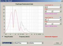
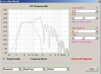
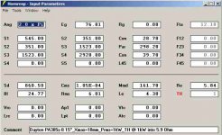
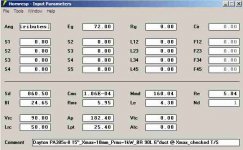
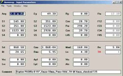
I'll attach two Hornresp simulations which (by accident) ended up @ about the same SPL around 40-70Hz when driving the PA385S to Xmax.
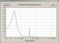
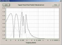
The BR needs Eg=72V to reach Xmax, and the TH Eg=49.3. @ 40Hz the Br's port particle velocity (input and output) is still quite high (~41 m/sec), getting below 15 m/sec around 60Hz. The TH throat/mouth particle velocities never get past 7 m/sec. We can safely assume that there will be higher losses in the BR that the simulation does not show.
At the impedance minimum around 39Hz the BR consumes 863 W. The TH needs 408 W @ 30Hz and 192 W @ 65 Hz. The reduced power input should result in much improved thermal behaviour for the TH, and the TH should have superior cooling characteristics through the placement of the magnet assembly in the mouth. There should be higher power compression in the BR as it is using more power to get to the same SPL, this in turn leads to even higher power needs when we are looking @ actual measurements.
While the BR is free from throat compression (distortion) it does have port compression (distortion), the TH does have much more favorable particle velocities.
The size of the radiating surfaces is much larger in the TH which should provide it with improved radiation resistance over the BR.
Anyway, those are substantial differences which should favor the TH, but, as Tom Danley has said measurements trump simulations. Have you had a chance to measure the distortion of the TH-118?
Regards,
Post #15: "Tom Danley uses a larger S1 in many of his TH designs, the Xoc1 TH-18 is a good copy of the DSL TH-118, the SS15 is similar but does not share some of the attributes.
In every TH I have measured, distortion has been higher per given excursion than the same driver in a BR, what "different distortion mechanisms" are you referring to?"
It's interesting that in the TH-118 DSL uses two braces in the first vertical duct section coming from the throat. and from a previously shown picture of the throat/duct entry (posted by Djim, it has since been censored) a lot of effort was put into creating a strong probably cone corrected driver interface. To compare a BR to a TH similar construction standards should be used for both boxes to prevent problems w/ the enclosures to distort the data.
I'll attach two Hornresp simulations which (by accident) ended up @ about the same SPL around 40-70Hz when driving the PA385S to Xmax.
The BR needs Eg=72V to reach Xmax, and the TH Eg=49.3. @ 40Hz the Br's port particle velocity (input and output) is still quite high (~41 m/sec), getting below 15 m/sec around 60Hz. The TH throat/mouth particle velocities never get past 7 m/sec. We can safely assume that there will be higher losses in the BR that the simulation does not show.
At the impedance minimum around 39Hz the BR consumes 863 W. The TH needs 408 W @ 30Hz and 192 W @ 65 Hz. The reduced power input should result in much improved thermal behaviour for the TH, and the TH should have superior cooling characteristics through the placement of the magnet assembly in the mouth. There should be higher power compression in the BR as it is using more power to get to the same SPL, this in turn leads to even higher power needs when we are looking @ actual measurements.
While the BR is free from throat compression (distortion) it does have port compression (distortion), the TH does have much more favorable particle velocities.
The size of the radiating surfaces is much larger in the TH which should provide it with improved radiation resistance over the BR.
Anyway, those are substantial differences which should favor the TH, but, as Tom Danley has said measurements trump simulations. Have you had a chance to measure the distortion of the TH-118?
Regards,
Attachments
- Status
- This old topic is closed. If you want to reopen this topic, contact a moderator using the "Report Post" button.
- Home
- Loudspeakers
- Subwoofers
- Compact 2x15" PPSL Using Dayton PA385-8 Drivers