I got the wiring of my power umbilical wrong and sent reversed voltage to the chips. They smoked in about 2 seconds. I installed 2 new chips fix the umbilical and it powered up fine.
I have .106 dc on both channels. It's a bit higher than the last amp i built. only difference between the two is I'm using an input resistor on the new one.
I'm wondering if the capacitors could have been damaged by having reverse polarity for a couple seconds. If so, could that cause the dc offset to be higher?
cure for mistakes like that.
fit a 1n400x diode across one of the main electrolytic decoupling caps mounted on the PCB and fit another to the other half of the dual supply.
You can also fit a 1n400x from each power rail to the output.
These 4 diodes save a lot of damage if the PSU is ever swapped around and can help with IV protected amplifiers driving dynamic (VC) speakers.
Just finished my Audio Sector kit last night and it's working wonderfully. It's a dual mono arrangement with the Twisted Pear USB receiver/DAC as the input device. I use it with my computer. I put so much capacitance in the power supply that I can flip off the power and it still plays for a while!
Thanks Andrew! Great tip.
I'm still curious about the reverse voltages damaging capacitors. Is that a possibility after 2-3 seconds?
I'm still curious about the reverse voltages damaging capacitors. Is that a possibility after 2-3 seconds?
Damage is very possible.
Remove at least one leg of each and reform them, noting how the reforming current varies over 24hrs.
Remove at least one leg of each and reform them, noting how the reforming current varies over 24hrs.
A couple of seconds won't probably create any damage, just use them. If the cap is rounded at the top, then you should react.
Last edited:
A couple of seconds won't probably create any damage, just use them. If the cap is rounded at the top, then you should react.
They look fine. Didn't get hot or do anything weird.
I got the wiring of my power umbilical wrong and sent reversed voltage to the chips. They smoked in about 2 seconds. I installed 2 new chips fix the umbilical and it powered up fine.
I have .106 dc on both channels. It's a bit higher than the last amp i built. only difference between the two is I'm using an input resistor on the new one.
I'm wondering if the capacitors could have been damaged by having reverse polarity for a couple seconds. If so, could that cause the dc offset to be higher?
As it was explained here: http://www.diyaudio.com/forums/audi...-kit-building-instructions-5.html#post1524877 the actual offset will depend on a particular chip, and varies sometimes significantly, from sample to sample.
The caps are fine.
400v transformer?
Hey guys, super quick noob question here.
I originally ordered the AN 3222 (300va) transformer, but they are out of them so I got it replaced with the AN 4222 (400va).
1) do I need to change anything in the classic gainclone kit? I don't want to pop anything.
2) I ordered the dual mono stuff, can I supply both sides with his one transformer?
Thanks guys!
Nothing needs to be changed when using 400VA transformer.
You can supply both sides with one transformer, but depending on a layout, you may experience some hum.
Preferred setup with a single transformer was presented here: http://www.diyaudio.com/forums/audi...-kit-building-instructions-4.html#post1518369
You can supply both sides with one transformer, but depending on a layout, you may experience some hum.
Preferred setup with a single transformer was presented here: http://www.diyaudio.com/forums/audi...-kit-building-instructions-4.html#post1518369
dual mono lm4780
I have read multiple conflicting opinions about using two transformers in one enclosure, as in one transformer for each channel in a dual mono configuration. Some say there is no problem if grounded properly and the wiring and transformers are isolated from the pcbs and signal. Other opinions state there is always hum and no ground configuration will totally eliminate this. My current plan is to use one antek AN3222 transformer (with the steel antek covers) per channel using the audio sector lm4780 pcbs with simplified wiring. My enclosure is rather large and I can shield or isolate all wiring if necessary to avoid unwanted noise. So I suppose my questions are.
1. Am I asking for trouble with my current plan or will some simple steps avoid any unwanted issues.
2. Should I just go with one transformer and save the other for another project (I already have all of the previously mentioned items)
3. If a unique ground configuration has been successful with these boards I would appreciate a link to a pic or diagram. I have searched and read audio component grounding and interconnection. I just did not find anything specific to my build
I apologize Peter if this is the wrong place for this question or if it has been covered before. And of course I am not unwilling to try different options and see what works. Thanks in advance to all.
IMO your fine either way. I have tried both single and dual mono with my LM3875.
I have used the kit rectifier boards as well as some KBPC diodes.
Do whatever you like, the amp can be quiet in either setup, no different then any other amplifier in this respect. IMO.
I have used the kit rectifier boards as well as some KBPC diodes.
Do whatever you like, the amp can be quiet in either setup, no different then any other amplifier in this respect. IMO.
Low hum from trafos
Hi,
first of all thank you Peter and all of you for giving me the chance to build with your help my amps.
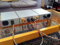
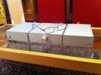
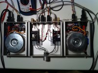
I built my third amp based on the Audiosector kit.
In particular this one uses the premium kit in dual mono configuration, the configuration similar to the 47 Labs Gaincard.
It sounds extremely good and I am very very satisfied. It incredibly improved the transparency of my diy Jordan MLTL speakers.
I only had to put the small caps at the chip input as suggested in post #51 because of the RF noise which now is completely disappeared.
No noise is now coming from the speakers.
I can only hear a very low hum when I put my hear very near the PSU.
Is this just a usual noise of the trafos or is it due to a ground loop?
I assumed that ground loop noise should come from the speakers.
Thank you for your help
Renato
Hi,
first of all thank you Peter and all of you for giving me the chance to build with your help my amps.
I built my third amp based on the Audiosector kit.
In particular this one uses the premium kit in dual mono configuration, the configuration similar to the 47 Labs Gaincard.
It sounds extremely good and I am very very satisfied. It incredibly improved the transparency of my diy Jordan MLTL speakers.
I only had to put the small caps at the chip input as suggested in post #51 because of the RF noise which now is completely disappeared.
No noise is now coming from the speakers.
I can only hear a very low hum when I put my hear very near the PSU.
Is this just a usual noise of the trafos or is it due to a ground loop?
I assumed that ground loop noise should come from the speakers.
Thank you for your help
Renato
Attachments
Nice work!
Yes, a ground loop would hum from the speakers.
Some transformers make a very faint hum/buzz.
Yes, a ground loop would hum from the speakers.
Some transformers make a very faint hum/buzz.
Nice work!
Thank you. It is not beautiful like Audiosector Patek, but I am proud of it, of course. I am going to post the pictures on the chip amp gallery
Yes, a ground loop would hum from the speakers.
Some transformers make a very faint hum/buzz.
OK, I can survive with it: I do not listen to music with my ears on the PSU
Renato
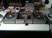
hi, i'm finally finished my premium gainclone (after 1 year+ of delay. lol). it is the premium version with caddock resistors, and audionote tantalum instead of riken gold. supply caps in amp module is BG F, and supply caps in PSU module is Panasonic FC 1500uF/35V (i have BG STD 1000uF/50V but decided to use the FC for testing). toroid is talema 2x25V/4.5A 225VA
it's been up and running for more than a week, easily more than 50 hours break in. i'm still not quite satisfied with this amp, as i think this amp sounds not as open as i want it to be (i have really high hope for this amp)
power ground has been well implemented in this gc (i followed peter daniel instructions very carefully and specifically)
i'm using 230V/2A slow blow fuse at the moment (SHIBA), will it sound better if i use 3A or 4A fuse instead of the current one?
thanks in advance
Last edited:
Joel, try 100uf caps instead of the large in board caps. Your fuse makes no difference but might someday fizzle on you. These caps can change the flavor of the amp a lot.
Power supply matters to. What r u using for a supply? I like to use about 60,000uf after the rectitude in a crc config. My chipamp is wonderful and only differences are those mentioned in this post and that I used different brands if components but these changed will be more obvious than brand swapping.
Go to my website and look at my 'resistor replacers'. You can buy but you can also build your own as I provide instructions. They take it up a notch as well.
Joel, try 100uf caps instead of the large in board caps. Your fuse makes no difference but might someday fizzle on you. These caps can change the flavor of the amp a lot.
Power supply matters to. What r u using for a supply? I like to use about 60,000uf after the rectitude in a crc config. My chipamp is wonderful and only differences are those mentioned in this post and that I used different brands if components but these changed will be more obvious than brand swapping.
Go to my website and look at my 'resistor replacers'. You can buy but you can also build your own as I provide instructions. They take it up a notch as well.
i specifically followed peter daniel build on the patek amp. after tracing most of his posts here in diyaudio, i came to the conclusion that he's using BG STD 1000uF on the PSU module
by crc configuration, were you referring to snubber?
Last edited:
- Home
- More Vendors...
- Audio Sector
- Commercial Gainclone kit- building instructions