Power up again with the bulb and measure the new and probably lower voltages of the PSU.
Power down and have a think.
What have you added or changed that is drawing so much current to pull the PSU down like that?
Can you go back a stage or two, or is there really only ONE change?
Power down and have a think.
What have you added or changed that is drawing so much current to pull the PSU down like that?
Can you go back a stage or two, or is there really only ONE change?
Thanks Andrew I will recheck things tomorrow when I get chance. I did'nt check the power supply voltages with the amp board connected but the bulb limited the mains voltage to about 90 volts. I will disconnect everything and recheck the pcb's with a magnifying glass.
Whoops I haven't done that in a long time😱 It was a solder bridge between two pins on the 4780. I connected the second channel and have an offset of 260mv on both channels. This is without the input connected the pot; wires just hanging. Will the offset drop when I connect it up?
If I short the input wires together and connect a dmm to the output the voltage rises and the bulb starts to glow. Have I cooked my chips?
With nothing connected the LM 4780's are running at 40 degrees Centigrade.
With nothing connected the LM 4780's are running at 40 degrees Centigrade.
Last edited:
What is your configuration (parallel, balanced)?
When everything is done right, shorting the input will not damage the chip.
Do you have it on a heatsink?
When everything is done right, shorting the input will not damage the chip.
Do you have it on a heatsink?
They are wired in parallel; all resistors fitted except Ro and with a single transformer and one p/s board. The signal input wires are not yet connected to a pot. Yes they are mounted on a piece of 10mm alluminium appro 12"x4".
Test it when you have the pot connected. You will also notice that with low volume settings, the offset is much less.
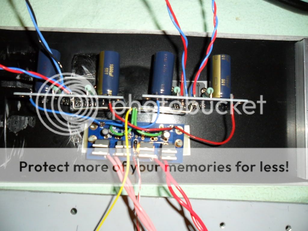
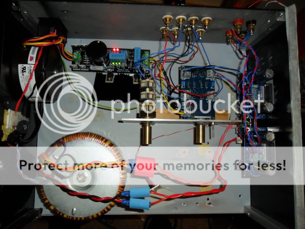
When idling, the temp shouldn't go as high. Post some pics, if you have a chance.
When idling, the temp shouldn't go as high. Post some pics, if you have a chance.
Thanks Peter .I just connected the LDR volume control and have these dc offsets.
Right -17.8 rising to -149
Left 9.3 rising to 138.6
Are these passable?
Right -17.8 rising to -149
Left 9.3 rising to 138.6
Are these passable?
The last time I posted a comment about variable output offset and described it as typical of a DC coupled amplifier, someone deleted my post.
Why would anybody suggest input caps if those voltages are only with attenuator and without any source connected yet? The input caps are needed in case the source producing the offset. I'm not familiar with LDR, but I don't think it's adding any offset?
Is it passable? How much offset do you read at normal listening levels? If you won't be exceeding 80mV or so, I would say it is passable. Otherwise you need NFB cap, not an input cap.
Is it passable? How much offset do you read at normal listening levels? If you won't be exceeding 80mV or so, I would say it is passable. Otherwise you need NFB cap, not an input cap.
Thanks for the response Peter. I connected the integrated GainClone to my cd player and a pair of 4" Tandy speakers and it plays music; spent the last hour listening to J J Cale live. I never thought to check the dc when listening; I take it thats what you meant? I'll listen again tomorrow.
Tried it out this morning and with the cd player and an old pair of speakers connected dc offset maxs out at 38mv on one channel and 46mv on the other. I've been listening to music for the past two hours and nothing overheats and sounds good too even through a crappy pair of 4" drivers.
...dc offset maxs out at 38mv on one channel and 46mv on the other.
Those offset values are perfectly fine.
What is the assembly just below the in/out RCAs?
Thats the Optivol LDR volume control[pcb's courtesy of dvbprojekt; unfortunately no longer available] with a Bib reg to its left.
- Home
- More Vendors...
- Audio Sector
- Commercial Gainclone kit- building instructions