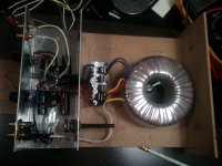
OK, connected everything, but there is something weird in my readings and apart from that: total silence.
My Transformer is a Amplimo 78016 300Va 2x25 6a
I have a setup with one rectifier board.
Measuring AC2 on the rectifier board reads 27v, as does AC1
Measuring V- PG- reads 35,7
V+ PG+ reads 35,9
DC ofset on speaker posts is 60mv right, 67,4 left
Any Ideas / suggestions?
My Transformer is a Amplimo 78016 300Va 2x25 6a
I have a setup with one rectifier board.
Measuring AC2 on the rectifier board reads 27v, as does AC1
Measuring V- PG- reads 35,7
V+ PG+ reads 35,9
DC ofset on speaker posts is 60mv right, 67,4 left
Any Ideas / suggestions?
you have high offset values of 60mV and 67.4mV
The other measurements all seem OK.
Are you using dual bridge rectifiers?
The other measurements all seem OK.
Are you using dual bridge rectifiers?
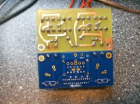
I do not exactly know what you mean with dual bridged rectifiers, I don't think so, but I included a pic to be sure. What I forgot to say inprevious post is that when I connect a source to the input and a test speaker, there is complete silence, not even some hum or whatever when I touch the plug....
😕
😕
Attachments
Hi,
dual secondaries and 8 diodes indicate dual bridge rectifiers.
That accounts for some of the extra voltage drop going from AC to DC.
A single bridge rectifier loses ~1.4V across the dual polarity supply.
The dual bridge rectifier loses ~2.8V across the dual polarity supply
dual secondaries and 8 diodes indicate dual bridge rectifiers.
That accounts for some of the extra voltage drop going from AC to DC.
A single bridge rectifier loses ~1.4V across the dual polarity supply.
The dual bridge rectifier loses ~2.8V across the dual polarity supply
OK, connected everything, but there is something weird in my readings and apart from that: total silence.
My Transformer is a Amplimo 78016 300Va 2x25 6a
I have a setup with one rectifier board.
Measuring AC2 on the rectifier board reads 27v, as does AC1
Measuring V- PG- reads 35,7
V+ PG+ reads 35,9
DC ofset on speaker posts is 60mv right, 67,4 left
Any Ideas / suggestions?
It all looks good.
Ok I have checked and double checked, and all above described values stay the same, I just do not hear anything when I connect a line input source. No sound, no hum, no noise. Just a kind of "thump" sound when I connect the speaker.
checked speaker, source, cable....
Any ideas?
checked speaker, source, cable....
Any ideas?
Measure your source to find out what it is sending.
Measure the amplifier input after connecting the source.
Then measure your amp output to see what it is amplifying.
At the least the DC offset should change if you connect an input.
Measure the amplifier input after connecting the source.
Then measure your amp output to see what it is amplifying.
At the least the DC offset should change if you connect an input.
Last edited:
Hi,
no change in output offset of a DC coupled amplifier when the input is open circuit or source loaded !
I think you have a break in continuity between your input socket and the amplifier input.
no change in output offset of a DC coupled amplifier when the input is open circuit or source loaded !
I think you have a break in continuity between your input socket and the amplifier input.
Hi,
I think you have a break in continuity between your input socket and the amplifier input.
That would mean no connection between the points in pink/purple on attached picture, right? Those points are according to my multimeter well connected... as are the ones in green btw...
Attachments

insert an RCA ended interconnect to one input.
Attached one probe to the hot pin at the far end.
Attach the other probe to the soldered joint of the next component down the hot trace from the coax input.
This will check for continuity through the RCA plug socket, through the RCA soldered joint, through the coax, through the input soldered joint and into the copper trace that is you hot input.
Move the probe from the PCB to the chassis and/or the central ground (other probe still attached to hot interconnect pin). Check continuity from hot input to audio ground. If this is shorted then no signal to amplify and no change in the DC offset conditions with alternative connections.
oowwwwwww... that was sooo stupid! R1 is optional, so I left it out, but forgot the wire... tnx Andrew for your tips, that did the trick!
First Impression: LOUD! (no attenuator)
Second Impression: eehh no Let's wait a few days...
First Impression: LOUD! (no attenuator)
Second Impression: eehh no Let's wait a few days...
"first impression LOUD."
What happened to checking output offset before and after connecting your source?
What happened to checking output offset before and after connecting your source?

Today all the hard work (at least for a newbe like me) fell into place. Damn this amplifier sounds good! All the clichés are true: musical, lively, open, tight...
Iam so happy I started this project, and ever so glad you guys pulled me through.
Big thanks to Peter especially, but also all the others who had to put up with my questions...
Thank you for the music!
Iam so happy I started this project, and ever so glad you guys pulled me through.
Big thanks to Peter especially, but also all the others who had to put up with my questions...
Thank you for the music!
I'm still trying to figure out how to build a nice chassis, but the amp sound very very good and I'm very please with it.
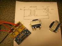
Have someone ever tried a circuit like this to turn on and off the amp?
Signal Detecting Auto Power-On Unit
And have someone try this instead of a heatsink?
Thermoelectric Peltier CPU PC Cooler 12V TEC Heatsinks - eBay (item 230565372083 end time Jan-18-11 19:53:42 PST)
I plan to use those two with a old 12V DC transformer that was with an old phone.
Thank you Peter for this great amp!
I use 2x 18-0-18v 120VA (Dual rectifier boards) to great effect on one of Peters LM3875T premium kits, and I am treated to a very detailed & transparent presentation. Into an 8ohm load, the amp will not clip, even at full volume (although I do use a shunted attenuator, which has a 47k metal film shunt resistor in line with the input). What really surprise me is that the amp doesn't get hot unless it is pushed to the limit. At low volume levels, it barely gets warm.
I often find people can be a little stuffy about the humble Gainclone, although I don't understand why. The LM series of audio chips (LM1875,3875 etc) are truly wonderful designs. Properly implimented, they are very capable of holding their own against more expensive commercial amplifiers, which suits me just fine. 🙂
I often find people can be a little stuffy about the humble Gainclone, although I don't understand why. The LM series of audio chips (LM1875,3875 etc) are truly wonderful designs. Properly implimented, they are very capable of holding their own against more expensive commercial amplifiers, which suits me just fine. 🙂
- Home
- More Vendors...
- Audio Sector
- Commercial Gainclone kit- building instructions