Peter Daniel said:Of course, don't forget about the fuse and use slow blow version. With 300VA transformer and no soft start, at least 4A rating is required (with 115V mains). In some instances even that blew occasionally so I normally use 5A SB fuses.
For 230V regions that would be half the fuse value.
Hi Peter,
I'm a little confused (pardon the pun) about the fuses for 240v supply. Half meaning 2 or 2.5 Amp or half meaning 8 or 10Amp?
Many thanks
Lucas
Amplifier Interference
Also, I have a problem. I have built one of Peter's kits. It sounds great, but I am getting the exact same oscillation through my speakers I got from my old amp (which I thought was buggered). Even without a source connected. So, I thought, hmmm, the speakers? the speaker cable? So unlikely? this is a computer-like oscillation. It turns out that I have these British Telecom Broadband socket communicators, that basically use mains electricity to communicate with each other, and put a horrible and quite loud computer-ish cricket chirping noise into my mains electricity. It's really pretty loud by anybody's standards. How do I get rid of such oscillation in my power supply? Bigger capacitors? I have some 4700uf 63v caps, designed for Hi-fi applications. Should that resolve things?
Many thanks
Lucas
Try to install a small cap as described here: http://www.diyaudio.com/forums/showthread.php?postid=1516522#post1516522
With higher mains voltage, the current is lower, so fuse value should be reduced.
With higher mains voltage, the current is lower, so fuse value should be reduced.
Peter Daniel said:Try to install a small cap as described here: http://www.diyaudio.com/forums/showthread.php?postid=1516522#post1516522
With higher mains voltage, the current is lower, so fuse value should be reduced.
Thanks Peter. I'm not talking about pops and switch noise though. This is quite a severe computer-like noise caused by intentional mains noise by my broadband/digital tv provider. Will a snubber system work to help reduce this problem, and if so, what do you recommend?
Regarding the fuses, I ask because the 2.5Amp fuses have been popping every other time I switch the amp on!!! (2x20v 300VAC) I will order some 3.15Amp ones then...
Many thanks
Lucas
P.s. I can hear that the amp is very alive and "youthful" sounding. Thanks for putting the kit together!
You may try Zobel, checking the small cap wouldn't hurt either. As to Zobel, it is 2R7 and 0.1uF.
If the fuse is popping, try larger value.
If the fuse is popping, try larger value.
transformers and motors require the fuse to be rated at aboutLucasAdamson said:the 2.5Amp fuses have been popping every other time I switch the amp on!!! (2x20v 300VAC) I will order some 3.15Amp ones then...
VA * 3 / 240, in the UK.
For 300VA that comes to 4A.
It may start repeatedly on a T3.1A fuse.
Both these fuse values can pass double their rating for many seconds, even minutes, before rupturing.
Member
Joined 2006
Hi Peter.
In my active system, I use 1,000F FCs for the GCs and they sound great.
For the mid/high channel, I have been thinking of using 100 uF BG N at the chip and some 1,000u F at the power supply side instead. Would you say that will give a greater improvement, in what way, worth it?
Thanks!
In my active system, I use 1,000F FCs for the GCs and they sound great.
For the mid/high channel, I have been thinking of using 100 uF BG N at the chip and some 1,000u F at the power supply side instead. Would you say that will give a greater improvement, in what way, worth it?
Thanks!
Hello CFT, I experimented with some capacitors value too.and what I found out was: using big caps on the power supply will give more bass.I try 4.7uf,10uf,1,000uf,2,000,10,000uf and 20,000uf. Right now I am using 20,000uf per channel and the sound is fantastic.some people say putting more capacitance will loose some tonal specially on the midrange frequency. I tell you, I must be loosing some hearing because I only hear improvement (bass) using more capacitance.The best way to hear the difference is using "alligator clips" and start testing capacitors (start from small to big values).maybe you like the sound with small values. Good luck.
Maybe they give more bass, but there are many aspects to the quality of the bass and IME big caps never worked well, of course that is also system dependant.
As to small caps at the chips, I only experimented with BG N 100/50 and they worked much better for mids and highs comparing to larger caps: more immediacy, purity and refinement.
See some of my comments from the past:
http://www.diyaudio.com/forums/showthread.php?postid=574431#post574431
http://www.diyaudio.com/forums/showthread.php?postid=581230#post581230
Hi Peter
Would there be any problem (in terms of grounding/hum) with a
3-chassis setup like this:
center- patek style power star ground layout for amp boards
left- 300 VA TR into rec. brd. then out umbil. to L amp inputs
right- 300 VA TR into rec. brd. then out umbil. to R amp inputs
with the ground wires from L & R psu's connecting to the thick copper star joining the amp boards
Peter Daniel said:You may try Zobel, checking the small cap wouldn't hurt either. As to Zobel, it is 2R7 and 0.1uF.
Can anybody explain or point me to info on installing a Zobel network, and what I'm trying to achieve with it? Will it make my amp more mediocre? That would be a shame...
Many thanks
Lucas
Well, if you check this thread, it may make you believe that the amp needs a Zobel: http://www.diyaudio.com/forums/showthread.php?s=&threadid=39039&highlight=
However, in well integrated systems, Zobel can actually degrade the sound, ask Nuuk 😉
If you run separate PS, there is no need to connect both channel grounds as in Patek amp; run them separately all the way. Here's an example of such amp.
However, in well integrated systems, Zobel can actually degrade the sound, ask Nuuk 😉
ppapcro said:Hi Peter
Would there be any problem (in terms of grounding/hum) with a
3-chassis setup like this:
center- patek style power star ground layout for amp boards
left- 300 VA TR into rec. brd. then out umbil. to L amp inputs
right- 300 VA TR into rec. brd. then out umbil. to R amp inputs
with the ground wires from L & R psu's connecting to the thick copper star joining the amp boards
If you run separate PS, there is no need to connect both channel grounds as in Patek amp; run them separately all the way. Here's an example of such amp.
Hi
which setup of the lm4780 kit is sonically better, paralleled or bridged?
I'd like to use it as a sub woofer amp. Should I use bigger caps or implement the snubber?
which setup of the lm4780 kit is sonically better, paralleled or bridged?
I'd like to use it as a sub woofer amp. Should I use bigger caps or implement the snubber?
In my experience, bridged is better, but you need a balanced source and be sure that speaker impedance does not go below 8 ohm. Otherwise you have no choice but to go paralleled.
Snuber is recommended only with big caps, so go with big caps first and then try a snubber.
Snuber is recommended only with big caps, so go with big caps first and then try a snubber.
Earthing again
Hi
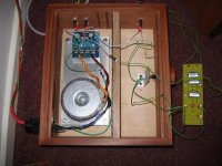
I've built a premium kit to be used with Oris horns boosting a bass driver,thanks Peter for the quick delivery.
The amp is in a mono config feeding a crossover for the horns.I'm getting a low level hum.
I have the power earth connected to the chassis.What should be earthed in this arrangement.Hopefully the pic should show the connections
Regards
Rob
Hi
I've built a premium kit to be used with Oris horns boosting a bass driver,thanks Peter for the quick delivery.
The amp is in a mono config feeding a crossover for the horns.I'm getting a low level hum.
I have the power earth connected to the chassis.What should be earthed in this arrangement.Hopefully the pic should show the connections
Regards
Rob
Attachments
Quick edit the output of the crossover feeds the chipamp and + and - is the input,Output is from pin 2 of the pot and - on the board.have tried various earthing arrangements.
Thanks
Rob
Thanks
Rob
Hi,
the secondaries look like insulated solid core.
If they are, replace with longer flexible stranded, still twisted.
Now you may have enough lead flexibility to rotate your toroid on it's mounting bolt. This may affect the hum by pointing the worst field spikes away from the sensitive circuits. Rotate to minimise hum and then consider whether you need/wish to shorten the flexy leads.
The mains Safety Earth should be shortened and bolted next to the incoming mains location.
The ground attached to that existing bolt can stay where it is.
It might be worth trying a wire link or a cap link from the metal pot support back to the Safety Earth plate.
How warm is it going to get inside that insulated box when the lid is secured? My guess is that everything inside will slowly cook even with just 5W of losses shared among all those components. Maybe 10 to 15W of losses, try measuring the quiescent consumption with no load.
hi,peter
I am very interest in you amp. I want to buy a 3875 kit for my ProAc 2.5.
please give me suggestion.
thanks.
I am very interest in you amp. I want to buy a 3875 kit for my ProAc 2.5.
please give me suggestion.
thanks.
Peter Daniel said:And between V- and PG- (black probe on PG)
If we measure approx. +/- 20V (positive will be lower because of LED) we are ready to connect amp boards.
Please note that voltages are much lower than expected beacuse of lack of smoothing caps.
If you have 10uF caps installed on rectifiers board both voltages would exceed 30V DC
hi,peter
I am very interest in you amp. I want to buy a 3875 kit for my ProAc 2.5.
please give me suggestion.
thanks.
Thanks AndrewT,the amps dont get even remotely warm the bass drivers are quite efficient.
Waiting on some stepped attenuators before I can mount everything properley,interesting re the box layout I hadn't really thought of that.
I'm wondering as its a wooden box should the signal earth from the crossover and SG and CHG on the chipamp be connected to the power supply earth or just connected together ?
Regards
Rob
- Home
- More Vendors...
- Audio Sector
- Commercial Gainclone kit- building instructions