You do have a source selector though, otherwise how do you switch between sources?
If so, turn selector to turntable first and then switch off the CD 😉
The thermistor will not help here, it's merely there to isolate circuit ground from chassis ground and the idea of using it came from First Watt amps.
If so, turn selector to turntable first and then switch off the CD 😉
The thermistor will not help here, it's merely there to isolate circuit ground from chassis ground and the idea of using it came from First Watt amps.
carawu said:Jan,
try 300pF PS between Pin 7 & 8.
Thanks guys!
One more question to Carawu: forgive me my little knowledge, but what does PS and pin 7 and 8 stands for?
best wishes
jan ove
PS could stand for polystyrene cap: http://www.diyaudio.com/forums/showthread.php?postid=1516522#post1516522
Peter Daniel said:PS could stand for polystyrene cap: http://www.diyaudio.com/forums/showthread.php?postid=1516522#post1516522
Thanks again. I will try this as soon as I got some spare time😉 My wife wants me to paint the fence in the garden :

best
jan ove
I'm rather lazy, you see
I will try this as soon as I got some spare time My wife wants me to paint the fence in the garden
Karma! 😀
thumper here
Peter,
Thanks for the direct, this is what I intend to do but with all four amplifiers on each side. One slight problem is getting hold of thermistor CL-60 - they are not sold here in the UK! Farnell will take the order but I have to then pay a premium ($30) for them ordering them from the states! So until I can get hold of some I will use your original method of connecting to the groung earth with a 10R resistor.
Alan
Thanks for this superb tutorial, Peter, but color me dense...
I can't figure out where R1 is (or goes). Is there a posted photograph showing either the wire, resistor, or cap soldered in place? I have four resistors on my board/s, can see the position for Rz(obel), and can see R1 in the diagram (Post #3).
I have a PSU question, too. I chose to power two amp boards in stereo config with one Avel 250VA 25V-25V toroid in a separate cabinet. Is it best to also house the rectifier board with the toroid? Or should I put it close to the amp boards as demonstrated here? What are the pros/cons of each?
Also, if I house the rectifier board with the toroid, how many wires do I need in my umbilical (at least four, of course)? I see your elegant Patek arrangement showing only four wires in two photos, whereas the example integrated amp in this tutorial shows two grounds to the star and four other wires to the boards.
Lastly: if I add two fast-blow fuses (for initial testing), do I still need the light bulb? (I've tested the PSU with the LED. It glows. Nothing smokes.)
David Barnett in SW FL
Vautrin said:I can't figure out where R1 is (or goes). Is there a posted photograph showing either the wire, resistor, or cap soldered in place?
R1 is the first ressitor on the left in this picture: http://www.diyaudio.com/forums/attachment.php?s=&postid=1508848&stamp=1210697477
Vautrin said:I have a PSU question, too. I chose to power two amp boards in stereo config with one Avel 250VA 25V-25V toroid in a separate cabinet. Is it best to also house the rectifier board with the toroid? Or should I put it close to the amp boards as demonstrated here? What are the pros/cons of each?
Also, if I house the rectifier board with the toroid, how many wires do I need in my umbilical (at least four, of course)? I see your elegant Patek arrangement showing only four wires in two photos, whereas the example integrated amp in this tutorial shows two grounds to the star and four other wires to the boards.
If amp and PS are in separate enclosures, I would suggest to place rectifiers with the transformer, that way you will have only DC in the amp. This may not be really critical, as I've built amps with rectifiers right beside the chip (see below) and they performed well, but placing the diodes in a PS enclosure is a common practice.
There are 4 wires in the umbilical: V+, V- and two grounds separate for each rail. While the example integrated amp had separate power wires for each channel (that's why you see 6) the Patek has power wires run from one channel to another channel (board).
An externally hosted image should be here but it was not working when we last tested it.
Eureka! It all just finally 'clicked'.
My God, this is the fastest, most thorough and informative response I've received in my two decades on internet . Thanks again, Peter. This project is the most fun and stimulating thing I've done in years.
David in SW FL (Venice - "God's Waiting Room")
My God, this is the fastest, most thorough and informative response I've received in my two decades on internet . Thanks again, Peter. This project is the most fun and stimulating thing I've done in years.
David in SW FL (Venice - "God's Waiting Room")
Vautrin said:The fuses would be on the DC side, between the rectifier board and the amps. (per Nuuk)
I'm always against placing fuses on the DC side, because if one fuse fails, you will have DC voltage at your speaker, as mentioned here: http://www.diyaudio.com/forums/showthread.php?postid=1521403#post1521403
This may inevitably damage your woofers. It is OK for testing, but not with your speakers connected.
To be honest, I never used light bulb method myself, I always use Variac to bring the voltage slowly up: http://www.diyaudio.com/forums/showthread.php?s=&postid=1518281&highlight=#post1518281
If you didn't make any mistakes while assembling the boards, there is a great chance everything will work fine right from a start. Make sure that power wires are not mixed up and always wear safety glasses: they will protect your eyes in case components suddenly explode (like improperly mounted electrolytics).😎
"I'm always against placing fuses on the DC side, because if one fuse fails, you will have DC voltage at your speaker..."
Makes sense. I'll nix the fuses and borrow (or buy) a variac.
"If you didn't make any error while assembling the board, there is a great chance that everything will work fine right from a start."
I meticulously soldered under the stereomicroscope I use for stone setting/engraving so I'm pretty sure everything's ready for the electrons. And you can be sure what's left of my presbyopic & diabetic eyes will be well-protected. Thank you for your concern. Safety is part of the system.
David in Venice, FL
Because I cannot yet begin a new thread, I'll post here (with any due nonsequiterization apologies frontloaded).
Finished the Audiosector LM3875 Classic kit last evening and couldn't be happier. It powered perfectly and silently (no hum, no thump, nothing), testing well within range for both channels and handling its first CD ( Oscar Peterson at the Blue Note) so cleanly and musically I was stunned. Fast and sensitive. Pure, but not cold. The piano sounded like, well... OP's piano. Ray Brown's bass and Herb Ellis' guitar presented remarkably better than I'd ever heard either. But the most striking thing overall was the sheer naturalness and lucidity to the thoroughly musical experience. Subtle passages were subtler, lively passages livelier with more detailed instrumental separation than ever (for me). Everything's so detailed, less challenging. Like new glasses for my ears.
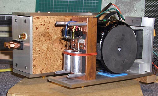
I chose to build a separate power supply using an Avel-Lindstrom 250VA 25V-25V toroid and one of the rectifier boards. The pot is the excellent PEC 50k carbon stereo model from Digikey. The chassis for each cabinet is 1/2" 6061 aluminum paired (stays cool) with cabinet walls of 1/2" bleached Baltic Birch plywood stacked to show the laminations horizontally, a look I've been lately exploring.
The speakers, little 4" Dayton RS100S-8 full range drivers, although not fully broken in, sound terrific so far. I've temporarily mounted them OB in 1/4" hardboard panels. Surprisingly easy to listen to these. The bass is better than I'd have expected, clear and detailed. I'm hopeful that speaker cabinets will bring it forward a bit, but it's not a deal breaker. Maybe some Jordans later, but for now, I'll keep them. I'd like to know what others are doing with these drivers but as they're still fairly new, I'll have to be patient, I suppose.
I'd encourage anyone reading this who is still on the fence regarding gainclone building to leap in and do it. With these kits and the instruction here, it's entirely doable and truly rewarding.
Thanks again to DIYaudio and esp. thanks to Peter for the kits, this tutorial and the outstanding support.
David in SW FL
Finished the Audiosector LM3875 Classic kit last evening and couldn't be happier. It powered perfectly and silently (no hum, no thump, nothing), testing well within range for both channels and handling its first CD ( Oscar Peterson at the Blue Note) so cleanly and musically I was stunned. Fast and sensitive. Pure, but not cold. The piano sounded like, well... OP's piano. Ray Brown's bass and Herb Ellis' guitar presented remarkably better than I'd ever heard either. But the most striking thing overall was the sheer naturalness and lucidity to the thoroughly musical experience. Subtle passages were subtler, lively passages livelier with more detailed instrumental separation than ever (for me). Everything's so detailed, less challenging. Like new glasses for my ears.
I chose to build a separate power supply using an Avel-Lindstrom 250VA 25V-25V toroid and one of the rectifier boards. The pot is the excellent PEC 50k carbon stereo model from Digikey. The chassis for each cabinet is 1/2" 6061 aluminum paired (stays cool) with cabinet walls of 1/2" bleached Baltic Birch plywood stacked to show the laminations horizontally, a look I've been lately exploring.
The speakers, little 4" Dayton RS100S-8 full range drivers, although not fully broken in, sound terrific so far. I've temporarily mounted them OB in 1/4" hardboard panels. Surprisingly easy to listen to these. The bass is better than I'd have expected, clear and detailed. I'm hopeful that speaker cabinets will bring it forward a bit, but it's not a deal breaker. Maybe some Jordans later, but for now, I'll keep them. I'd like to know what others are doing with these drivers but as they're still fairly new, I'll have to be patient, I suppose.
I'd encourage anyone reading this who is still on the fence regarding gainclone building to leap in and do it. With these kits and the instruction here, it's entirely doable and truly rewarding.
Thanks again to DIYaudio and esp. thanks to Peter for the kits, this tutorial and the outstanding support.
David in SW FL

Originally posted by Peter Daniel . . . It so happens that I recently received an order for LM1875 amp . . .
Originally posted by Peter Daniel Sounds very good, in my testing setup.😉
Hi Peter. Yes, its very good. KUDOS!! I have a question: If one wants to use a preamplifier, which do you recommend?
Thanks man!
I'm not good with recommending preamps, as I don't have much experience with them. If you don't need extra gain, just install quality attenuator directly at amp's input, other than that I can only recommend S&B TX102 as that's what I'm using myself in two different systems.
- Home
- More Vendors...
- Audio Sector
- Commercial Gainclone kit- building instructions