as a matter of practice, i wear rubber slippers/shoes and clear safety glasses and step on wooden boards as a precaution when working on electronic/electrical gears...
and you are right, children or toddlers have no place anywhere near to your work station...
that was meant to be a joke......😉
and you are right, children or toddlers have no place anywhere near to your work station...
By the way, i don't think that any damage has been done here by anyone.
that was meant to be a joke......😉
I think that this discussion is not going to any end and i will quit here. There are already some good and working schematics how to build a working audio ground for the people who are interested and who can read. Any further advice depends strongly ont the real amplifier layout and without measurements it does not have merit do go any further.
you are correct, drawings are drawings, ideas if you will put into pen and paper,
to me what matters most is how you actually implemented the idea and whether or not it gave you the desired results....
i hate arguing about drawings, i'd rather see how it was actually implemented in a real amp....
imho, the Bonsai scheme is enough to go by....
he makes amps that are quiet, he must be doing it right....
The scheme I showed is by no means the only way.
I will take another careful look at DS approach and jn's input. If I can make it work, I will add it to the document.
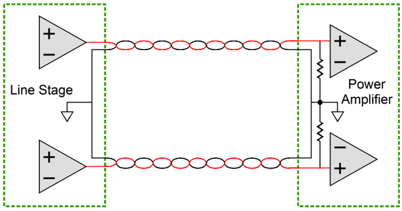
The basic rules for all schemes are the same: keep radiating/recieving areas as small as possible =twist the wires
Keep radiating cables away from recieving cables
Make sure ground loops cannot form, or, if unavoidable, mitigate them (screening, placement etc)
Avoid common impedance coupling mechanisms - use star ground or 'T'
Always earth your equipment
.
.
.
I will take another careful look at DS approach and jn's input. If I can make it work, I will add it to the document.
The basic rules for all schemes are the same: keep radiating/recieving areas as small as possible =twist the wires
Keep radiating cables away from recieving cables
Make sure ground loops cannot form, or, if unavoidable, mitigate them (screening, placement etc)
Avoid common impedance coupling mechanisms - use star ground or 'T'
Always earth your equipment
.
.
.
Make sure ground loops cannot form, or, if unavoidable, mitigate them (screening, placement etc)
how are they formed to begin with?
...a straight wire with another wire coiled around it...although the coiled wire does indeed produce flux when a current passes through it...the flux flows harmlessly in parallel with the straight wire and therefore induces no (or negligible) EMF in it.
Let the AC-twisted-coupled thing go, it doesn't matter anymore. Because the theories around here have now gotten downright bizarre. This is in addition to nullifying every high school science demonstration ever conceived.
Lookee, it doesn't matter whether a single conductor is straight, coiled, or formed into a likeness of Mickey Mouse. 1. Given current flow, a flux field will exist around that conductor. 2. A second conductor adjacent will be influenced by that field. 4. "Influenced" in this context means current will be induced in the second conductor.
Everybody write that down, and read it until you believe it.
In the stated case of a coil around a straight conductor, the induced current in the second conductor will be significant. It doesn't matter which is the first or second conductor, flux fields work the same way backward or forward.
If just a straight conductor crosses another straight conductor at a right angle, then induction will certainly be minimal, but whether it's negligible is a different discussion. There is no "zero induction" state.
Sorry, but the idea that "...flux flows harmlessly in parallel with the straight wire..." is just meaningless. That's not how a flux field works. To give just the barest notion of this (there's actually a lot more going on), below is an image from https://www.nde-ed.org/EducationReso.../CoilField.htm
Or if you want to believe otherwise, fine by me. But don't blame me when when all electrical phenomena stop happening when you're around.
Just in a brief sidebar, remember that all of this applies as well to DC as to AC. In the two different cases the question of a "varying" or "stationary" flux field arises, but the rules are the same.
.
Attachments
<<<Lookee, it doesn't matter whether a single conductor is straight, coiled, or formed into a likeness of Mickey Mouse. 1. Given current flow, a flux field will exist around that conductor. 2. A second conductor adjacent will be influenced by that field. 4. "Influenced" in this context means current will be induced in the second conductor.
Could there be one exception to this rule? That if the adjacent conductor is flowing an identical current in the opposite direction there is a cancellation of the magnetic field. Which would mean that there is no inductance or what ever you want to call it.
A transformer with a second primary connected out of phase would demonstrate this, there would be no voltage on the secondaries proving there is a cancellation.
do you have actual data as to the number of folks killed?
it seems to me that you and your kind seems to go around forums scaring people...
makes me wonder if you and the likes of you are really into building anything at all....
Where did I say that anyone was killed? Not trying to scare people at all, only that builders should understand what they are building and learn to recognise the dangers.
On your scheme the loop between Safe grounds are ideal ?
There are many reasons for don't consider the earthing ground and power rails ideal
with no voltage generators inserted between them .
Sorry, but the idea that "...flux flows harmlessly in parallel with the straight wire..." is just meaningless. That's not how a flux field works. To give just the barest notion of this (there's actually a lot more going on), below is an image from https://www.nde-ed.org/EducationReso.../CoilField.htm
If you look at your flux diagram you will see that in the centre of the coil the flux flows in parallel straight lines, so if you place a straight wire down the centre of the coil it too will be in parallel with the flux, so it does not cut any lines of flux, hence no induction into it. The same principle applies to a twisted pair even though the geometry of the situation is more complicated (i.e. less obvious). OK, nothing is ever perfect; there can always be some induction, but it is much less than if the wires, say, run directly side-by-side in parallel.
And as Mark pointed out, a twisted pair usually carries the same current in each wire but in opposite directions, so the flux fields cancel out, or very nearly so. You wouldn't normally twist a pair of wires which carry completely different signals.
Last edited:
Where did I say that anyone was killed? Not trying to scare people at all, only that builders should understand what they are building and learn to recognise the dangers.
this is not the first time you posted such remarks after i posted,
although i did not feel alluded to, i felt i must react....
death is permanent, make no mistake about it....
and anyone who does not recognize all the things that can go wrong and
do not know all the things required to build safely electronics appliances has no business tinkering with it....
Good, that's the feeling that will keep you alive and healthy. Someone who doesn't cringe when hitting the power switch is going to be in trouble sooner or later.
i know the dangers, i have been working tube amps with voltages in the 1kv range, sometimes it takes me days before i get the courage to turn on the switch, that is after i have gone over thru my work at least several times over...😎
i usually sleep over my work and come back the next day...
this is not the first time you posted such remarks after i posted,
although i did not feel alluded to, i felt i must react....
death is permanent, make no mistake about it....
and anyone who does not recognize all the things that can go wrong and
do not know all the things required to build safely electronics appliances has no business tinkering with it....
I reread the posts and I must apologise to AJT. I did not mean to say that whatever he build would be unsafe. It was my intention to say that whatever one builds it is two failures away from being dangerous. As an example, the car brakes and air-bags failing at the same time.
AJT, please forgive me for making such a mistake.

Could there be one exception to this rule?
No, none. You can tell by the way the universe hasn't stopped existing.
.
That is precisely what I tried to teach while I was a "techy" teacher.learn to recognise the dangers.
Then take action/s to mitigate the risks.
I remember the face of a visiting Pupil who entered my classroom on a school walk around.
This is a story I have recounted to many of my friends/acquaintances.
He stood still and open mouthed as he observed all the open cupboards with a multiplicity of tools for the working pupils,
then said "are we allowed to use these?"
From my knowledge of his background, I gathered he saw tools as something else !
He had not previously been trusted with "weapons" so freely available. He became my class pupil two days later.
If you look at your flux diagram...if you place a straight wire down the centre of the coil it too will be in parallel with the flux, so it does not cut any lines of flux, hence no induction into it.
You did know the subject is AC, not DC? Suggestion: further investigate "varying" or "stationary" flux fields.
.
You have just excluded ~99% of our Members from this hobby !....................and anyone who does not recognize all the things that can go wrong and
do not know all the things required to build safely electronics appliances has no business tinkering with it....
Some of us responsible Members will help other Members learn to stay alive.
death is permanent, make no mistake about it....
The dead ones can't report their failures.
Last edited:
No, none. You can tell by the way the universe hasn't stopped existing.
.
Can you explain why the transformer in my example has no voltage output.
Yes this applies for AC; when the current reverses, the flux still follows the same path as in your diagram, but in the opposite direction. It is always parallel to a straight wire in the centre of the coil.You did know the subject is AC, not DC?
Not quite. AC current induces voltage, not current.bentsnake said:4. "Influenced" in this context means current will be induced in the second conductor.
Some geometries can give zero induction in the ideal case, and negligible induction in many practical cases. That is why we use coaxial cable or twisted pair.If just a straight conductor crosses another straight conductor at a right angle, then induction will certainly be minimal, but whether it's negligible is a different discussion. There is no "zero induction" state.
Not certain what you mean by "all of this" but magnetic induction only occurs for varying currents, not steady DC.Just in a brief sidebar, remember that all of this applies as well to DC as to AC.
- Status
- Not open for further replies.
- Home
- Source & Line
- Analog Line Level
- Comment on Grounding Scheme?