What do you think the compression ratio is on this annular diaphragm:Also, the compression ratio is 8:1, which provides an airspeed of roughly 5,5 m/s at the phase plug with 91 dB, 400 Hz.
Any estimate of it's airspeed when the SPL is over 160dB ?
The noise floor has those peaks, as do all the harmonics.This speed through a non optimized, crudely printed phase plug could be the source. Still, It doesn't directly explain the peaks at 4 and 500 Hz.
Unless you plan to copy the all the patent details (annular diaphragm ect.) and sell the drivers, not much to be careful about.PS: as this design is related to the dcx464, which is patented. I'm careful with sharing details (drawings etc) which could cause indirect infringement of the patent.
Art

@weltersys thanks for the insights.
Also, would love to make this work my job. I found some loopholes in the patent which could be used for a commercial product.
Before getting too lost, i need to learn a lot about R&D in acoustic design before anything else, as you might have noticed.
Sometimes i feel like an apprentice again...Any estimate of it's airspeed when the SPL is over 160dB ?
True, but there is indirect infringement if i help others with my work/results to replicate the design/claims in the patent. I could share details, but it will need to be educational, not with the goal to get others to replicate the claims. For example, i cant share 3D files which can be used for manufacturing/3D printing.You could use the details in the patent for personal / research purposes without consequence.
Also, would love to make this work my job. I found some loopholes in the patent which could be used for a commercial product.
Before getting too lost, i need to learn a lot about R&D in acoustic design before anything else, as you might have noticed.
Last edited:
Late to the discussion but, my take on a low cost coaxial compression driver is far easier.
https://renkus-heinz.com/core-technologies/
So far I have made a 1" CoEntrant adapter and a 2". Simple conical expansion from the phase plug of the compression driver to the desired exit diameter.
What i haven`t tried yet is to design for a melamine plug in the ports for the midrange. That would qualify as a impedance miss-match device.
Attachments

Last edited:
Hi Nissep
large midrange holes! Did you make any off axis measurements you could share? I am quite interested as you have many midrange ports but they are so close that I am curious how much they really disturb the HF.
large midrange holes! Did you make any off axis measurements you could share? I am quite interested as you have many midrange ports but they are so close that I am curious how much they really disturb the HF.
Awesome work!Late to the discussion but, my take on a low cost coaxial compression driver is far easier.
https://renkus-heinz.com/core-technologies/
In the patent they call it the "passive low pass filter". It blocks the HF from entering the MF ports according to the patent. Im curious what the effect of your MF ports are on the HF as yours are large enough for HF to pass. Aka, do we realy need to make a "passive low pass filter"? Unity horns work without it.That would qualify as a impedance miss-match device.
For me to investigate the holes influence I simply need to make a cone and insert it. But from memory i don't think i did this.
To be honest, I`m terrible at keeping record of these tests I do.
Short attention span, and then I move on to next test shiny thing in my mind.
But 600-20000Hz low distortion from a 6" coaxial that at the time costed ~100usd.
I did test the 2" on a JBL 2380a clone and could replicate the data sheet. But I felt something was off, getting ear fatigue and blamed the horn.
So i moved on to a 1" version to use other horns.
Attachments
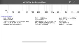
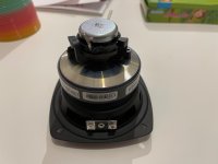
For people living in Europe here’s a cheap driver to fiddle with if anybody like to give a CoEntrant adapter a go.
https://www.thomann.se/the_box_pro_4_coax_speaker_mcx4.htm
https://www.thomann.se/the_box_pro_4_coax_speaker_mcx4.htm
Attachments

@Olombo
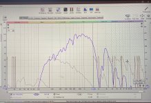
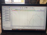
That was a processed result. So don`t let me fool you.
I simply was chasing a nice crossover point there.
That was a processed result. So don`t let me fool you.
I simply was chasing a nice crossover point there.
Attachments
Last edited:
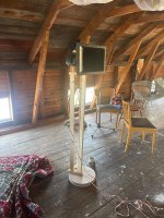
You wouldn't love it in the winter.. And that is mainly why that project lost momentum.Love your lab! 👍
To use a coaxial for MEH a is clever.
//
Some of this comes down to where you are operating. In the US, infringement is more tied to whether you are trying to profit from the replication. You mostly have free rein to make whatever you want as long as you don't sell it or damage the patent holder in some way.but there is indirect infringement if i help others with my work/results to replicate the design/claims in the patent
The EU doesn't give as much leeway, but my AI friend says: "Limited Exceptions Exist: Dutch and EU law do have some narrow exceptions, including: Experimental use: Use of a patented invention for experimental purposes relating to the subject matter of the invention (e.g., scientific research). . . .
Unlike in U.S. copyright law (or the broader U.S. attitude toward patent exemptions), the EU approach is more protective of the patent holder’s rights and does not recognize a general fair use or personal use exception. . . .
Practical Reality: While the law is strict, enforcement is often selective. It's unlikely that a patent holder would pursue a private individual for using a patented item at home unless there’s economic harm or visibility, but they legally could."
------------------------------------
Back to me talking:
Realistically, most companies are going to step over the "line" intentionally or unintentionally when doing research. You might be trying to determine whether the patent's description actually does what it claims or if your invention does it better, you might not know about a patent, or it may be impossible to understand what a patent is supposedly trying to do. I've had to deal with some lately where there was literally no way to understand what the "patent" was describing because the math was too poorly defined. I think that was intentional because prior art invalidates their patent, but if described in a convoluted enough way you just might squeak through and get a patent - yay!
In the end, prosecuting a home tinkerer would only make money for the patent attorneys, and trust me, they make plenty already. If you're doing something the patent holder doesn't like, a cease-and-desist letter is a more likely outcome, but even that is probably going to cost more than it's worth for someone that's obviously not trying to do anything sketchy. Some patents are also more about inflating a company's or university's IP portfolio, and a lot less about enforcement. In the only significant inbound patent suit I can remember from working at a company that had about 150 patents, the case was essentially nonsense but was settled with a relatively small royalty on our sales of a single item. I don't think it was worth anyone's time, except of course the lawyers - they've elevated billing to an art.
If you aren't interested in pursuing your own patents, a reasonable defense is often to find prior art in expired patents or disclosures that are similar to what you want to do. Older patents also tend to be more clearly and narrowly written, so you have a better chance of successfully making what they describe.
Last edited:
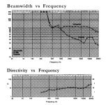
"Unity" was the name for Tom Danley's multiple entrant horns (MEH) while with Sound Physics Labs(SPL). Unity™ was also licensed to Yorkville Sound.Aka, do we realy need to make a "passive low pass filter"? Unity horns work without it.
"CoEntrant" was Renkus Heinz name for their MEH, which preceded the Unity series.
Like the Danley Sound Labs (DSL) "Synergy" MEH, or any driver with an enclosed space between it and the exit ports, the mid output exhibits a steep acoustic low pass filter, followed by a series of peaks and dips independent of those determined by the horn entry point.
Nissep's first attachment in #51 is fairly typical of that type of response, requiring the crossover frequency to be below ~1500Hz.
The more excursion the driver is allowed, the larger the enclosed air volume is, and the lower the frequency of the acoustic low pass filter.
Coax compression drivers like those produced by BMS or B&C require a high crossover point between the mid and high, so the enclosed air space between the mid diaphragm and phase plug has to be minimized to raise the acoustic low pass filter frequency, which then limits excursion and low frequency output potential.
The compromise between displacement and the acoustic low pass filter frequency determines usable bandwidth.
The tricky part is designing exits for the lower driver that don't screw up the response of the upper driver too badly.
Art
Last edited:
Update
I decided to keep my head down for a while till i had some results that matter. Have printed and tested 5 prototypes in the mean time. The last one, while playing music right before measuring, sounded verry different in a good way.
It also shows in the measurements.
For context:
Measurements on SB audience H280
1 meter mic distance
4,5 ms window
Burst decay and fourier waterfall are "normalized" with the EQ function of REW
Burst decay floor is -35 dB
fourier waterfall floor is -25 dB
Fr graphs are smoothed 1/12
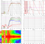
Fourier waterfall and decay HF


Fourier waterfall and decay MF


FR HF

FR MF

Polar HF

Polar MF

To be continued!
I decided to keep my head down for a while till i had some results that matter. Have printed and tested 5 prototypes in the mean time. The last one, while playing music right before measuring, sounded verry different in a good way.
It also shows in the measurements.
For context:
Measurements on SB audience H280
1 meter mic distance
4,5 ms window
Burst decay and fourier waterfall are "normalized" with the EQ function of REW
Burst decay floor is -35 dB
fourier waterfall floor is -25 dB
Fr graphs are smoothed 1/12
Fourier waterfall and decay HF
Fourier waterfall and decay MF
FR HF
FR MF
Polar HF
Polar MF
To be continued!
Note for the previous post: Measurements where at -32.5 dBfs. This means that at 2.83 V rms the MF driver would do 110 dB/1m...
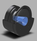
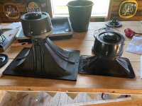
Here is a section view of the CCDIY.


The design has changed a lot compared to earlier pictures. The main change that made the biggest improvement whas cutting the dustcap off of the mid range (blue part resembles the space between diaphragm and phase plug). This made it possible to have even path lengths for the MF sound while having MF ports only 9 mm long. This in turn made it possible to make main port to the 1.4 inch exit shorter and smoother. The next improvement came from the late meeting point of the two HF slots. This, i think, reduces the interaction between the HF sound and the MF ports.
Fun fact: the phase plug, part between the HF and MF drivers, consists of 4 individual parts. This to ensure cleanly printed parts as it has a lot of overhangs.
In the first picture, it looks like the exit at the top is straight. This is caused by the section view. In reality its expanding to the full 1.4 inch exit.
Also visible in the top picture, are the reliefs in the top part for foam gaskets between it and the phase plug and sealing between the driver and the horn flange.
For my first project with a 3d printer, it has been a real eye opener. The speed at which prototypes can be iterated is insane. Also, when done right, tolerances are also easy to hit. For example: the space between the HF diaphragm and its phase plug is only 0.3mm and the clearance between the MF voice coil and the plug inside it is only 0.2 mm. I havent had to ad extra clearance by cutting or sanding.
As for now, the phase plug performance looks good. Still, a lot has to be done for the CCDIY to be completed:
Compression ratio needs to be evaluated. Have kept it at 8.3:1 for MF and 4:1 for HF. Want to know how it effects IMD and THD.
Thermal management is nowhere to be found.
MF rear chamber dampening is not yet exploited.
Listening tests should be conducted to evaluate the subjective performance. As my ears and brain are not as trained as most folks (and biased af), i will probably opt for alpha testing with forum members.
Would love to hear your take on this project/subjects
Here is a section view of the CCDIY.
The design has changed a lot compared to earlier pictures. The main change that made the biggest improvement whas cutting the dustcap off of the mid range (blue part resembles the space between diaphragm and phase plug). This made it possible to have even path lengths for the MF sound while having MF ports only 9 mm long. This in turn made it possible to make main port to the 1.4 inch exit shorter and smoother. The next improvement came from the late meeting point of the two HF slots. This, i think, reduces the interaction between the HF sound and the MF ports.
Fun fact: the phase plug, part between the HF and MF drivers, consists of 4 individual parts. This to ensure cleanly printed parts as it has a lot of overhangs.
In the first picture, it looks like the exit at the top is straight. This is caused by the section view. In reality its expanding to the full 1.4 inch exit.
Also visible in the top picture, are the reliefs in the top part for foam gaskets between it and the phase plug and sealing between the driver and the horn flange.
For my first project with a 3d printer, it has been a real eye opener. The speed at which prototypes can be iterated is insane. Also, when done right, tolerances are also easy to hit. For example: the space between the HF diaphragm and its phase plug is only 0.3mm and the clearance between the MF voice coil and the plug inside it is only 0.2 mm. I havent had to ad extra clearance by cutting or sanding.
As for now, the phase plug performance looks good. Still, a lot has to be done for the CCDIY to be completed:
Compression ratio needs to be evaluated. Have kept it at 8.3:1 for MF and 4:1 for HF. Want to know how it effects IMD and THD.
Thermal management is nowhere to be found.
MF rear chamber dampening is not yet exploited.
Listening tests should be conducted to evaluate the subjective performance. As my ears and brain are not as trained as most folks (and biased af), i will probably opt for alpha testing with forum members.
Would love to hear your take on this project/subjects
Last edited:
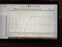
Bravo for keeping at it! Any ideas on that 3.3Khz dip on the tweeter? Related to the midrange ports or something else? Was it present in all of the prototypes?
Dont realy know. It was present in the first prototype, but it dissapeared with one of the prototypes and now has come back.Any ideas on that 3.3Khz dip on the tweeter?
I'd say offer some efficiency for performance if need be. There is plenty of it to go around. Following with great interest!
//
//
- Home
- Loudspeakers
- Multi-Way
- Coaxial Compression Driver DIY (CCDIY) discussion