Accepted input data length ( coded e.g. AC3 or not coded linear PCM) is 16 bit.sz_ahong said:Note: 1. Only 16-bit PCM streams are supported. For 20-bit or 24-bit PCM, the 4 or 8 least significant bits are ignored
at the datasheet page15.
It's only support 16-bit PCM?
Anybody can help me??
Re: I FINALLY FOUND A SUPPLIER!!! 🙂
Here you go bud. All the ST19AF08 chips you want. No license. No minimum. No hassle.
http://cgi.ebay.com/NEW-ST19AF08-SM...ryZ50915QQrdZ1QQssPageNameZWD1VQQcmdZViewItem
By the way...can anyone point me to the STA310 core (MMDSP+) instruction set?
Thanks
emuman100 said:All I need is the ST19AF08 and I'll have all the parts I need for the XM receiver as well.
Here you go bud. All the ST19AF08 chips you want. No license. No minimum. No hassle.
http://cgi.ebay.com/NEW-ST19AF08-SM...ryZ50915QQrdZ1QQssPageNameZWD1VQQcmdZViewItem
By the way...can anyone point me to the STA310 core (MMDSP+) instruction set?
Thanks
Time for me to share some great news, just couldn't keep it for myself a whole night 🙂
After some brakes and frustrations with the data sheet it creates sound and even for the setup some damn find sound.
DTS and DD all sound pretty fine.
2 days earlier the project got a jump start in finding Tomek article and download of the board and schematic in a Polish magazine. It is in Protel 99SE format. Get the files here.
This got the PLL filters right for me and apparently it was the only thing left of the schematic, the rest worked fine for months
The project is far from identical to that of Tomek. It is still very much vero and breadboard at this point.
So far only Left an Right channels have a DAC/IV attached to them, but for a first test it will be fine, there is data coming out of the other I2S data lines. The dac is a PCM1798 with 6xOPA132 IV following the dac data sheet.
The STA310 is controlled with a FTDI usb controller in I2C mode. This allowed for some register tweaking on the fly with a home brew VB program. Came in very handy for debugging the "fully" documented registers of the STA310 data sheet.
I'm now gonna bug you guys with some pictures, I'm just to damn proud this evening 😀
(Just hit the enter button once more, forbidden warning is bugging us)
First picture is the STA310 with the PLL filters and the FTDI usb chip.
http://www.wirdumonline.nl/DAC/01_STA310_USB.jpg
Very high end I2C cabling
http://www.wirdumonline.nl/DAC/02_I2S.jpg
DAC with IV, again the high-end I lines
http://www.wirdumonline.nl/DAC/03_DAC_IV.jpg
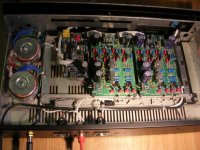
Power supply, nothing fancy, one regulator per supply, even a boring heatsink 😉
http://www.wirdumonline.nl/DAC/04_powersupply.jpg
How its all connected
http://www.wirdumonline.nl/DAC/05_overview.jpg
The program I made, just show a small part of the register values
http://www.wirdumonline.nl/DAC/06_vb_util.jpg
After some brakes and frustrations with the data sheet
it creates sound and even for the setup some damn find sound.DTS and DD all sound pretty fine.
2 days earlier the project got a jump start in finding Tomek article and download of the board and schematic in a Polish magazine. It is in Protel 99SE format. Get the files here.
This got the PLL filters right for me and apparently it was the only thing left of the schematic, the rest worked fine for months
The project is far from identical to that of Tomek. It is still very much vero and breadboard at this point.
So far only Left an Right channels have a DAC/IV attached to them, but for a first test it will be fine, there is data coming out of the other I2S data lines. The dac is a PCM1798 with 6xOPA132 IV following the dac data sheet.
The STA310 is controlled with a FTDI usb controller in I2C mode. This allowed for some register tweaking on the fly with a home brew VB program. Came in very handy for debugging the "fully" documented registers of the STA310 data sheet.
I'm now gonna bug you guys with some pictures, I'm just to damn proud this evening 😀
(Just hit the enter button once more, forbidden warning is bugging us)
First picture is the STA310 with the PLL filters and the FTDI usb chip.
http://www.wirdumonline.nl/DAC/01_STA310_USB.jpg
Very high end I2C cabling
http://www.wirdumonline.nl/DAC/02_I2S.jpg
DAC with IV, again the high-end I lines
http://www.wirdumonline.nl/DAC/03_DAC_IV.jpg
Power supply, nothing fancy, one regulator per supply, even a boring heatsink 😉
http://www.wirdumonline.nl/DAC/04_powersupply.jpg
How its all connected
http://www.wirdumonline.nl/DAC/05_overview.jpg
The program I made, just show a small part of the register values
http://www.wirdumonline.nl/DAC/06_vb_util.jpg
TriLithium said:Time for me to share some great news, just couldn't keep it for myself a whole night 🙂
After some brakes and frustrations with the data sheet
DTS and DD all sound pretty fine.
2 days earlier the project got a jump start in finding Tomek article and download of the board and schematic in a Polish magazine. It is in Protel 99SE format. Get the files here.
This got the PLL filters right for me and apparently it was the only thing left of the schematic, the rest worked fine for months
The project is far from identical to that of Tomek. It is still very much vero and breadboard at this point.
So far only Left an Right channels have a DAC/IV attached to them, but for a first test it will be fine, there is data coming out of the other I2S data lines. The dac is a PCM1798 with 6xOPA132 IV following the dac data sheet.
The STA310 is controlled with a FTDI usb controller in I2C mode. This allowed for some register tweaking on the fly with a home brew VB program. Came in very handy for debugging the "fully" documented registers of the STA310 data sheet.
I'm now gonna bug you guys with some pictures, I'm just to damn proud this evening 😀
(Just hit the enter button once more, forbidden warning is bugging us)
First picture is the STA310 with the PLL filters and the FTDI usb chip.
http://www.wirdumonline.nl/DAC/01_STA310_USB.jpg
Very high end I2C cabling
http://www.wirdumonline.nl/DAC/02_I2S.jpg
DAC with IV, again the high-end I lines
http://www.wirdumonline.nl/DAC/03_DAC_IV.jpg
Power supply, nothing fancy, one regulator per supply, even a boring heatsink 😉
http://www.wirdumonline.nl/DAC/04_powersupply.jpg
How its all connected
http://www.wirdumonline.nl/DAC/05_overview.jpg
The program I made, just show a small part of the register values
http://www.wirdumonline.nl/DAC/06_vb_util.jpg
No pics...
Forbidden
You don't have permission to access /DAC/05_overview.jpg on this server.
Additionally, a 404 Not Found error was encountered while trying to use an ErrorDocument to handle the request.
Apache/2.0.59 (Unix) mod_ssl/2.0.59 OpenSSL/0.9.7a FrontPage/5.0.2.2634 mod_perl/2.0.3 Perl/v5.8.5 Server at www.wirdumonline.nl Port 80
TriLithium said:I know, just hit the enter button once more in the address bar.
No help for me...
Changed host, Looks a lot better 🙂
First picture is the STA310 with the PLL filters and the FTDI usb chip.
Very high end I2S cabling
DAC with IV, again the high-end I lines
Power supply, nothing fancy, one regulator per supply, even a boring heatsink
How its all connected
The program I made, just show a small part of the register values
First picture is the STA310 with the PLL filters and the FTDI usb chip.
An externally hosted image should be here but it was not working when we last tested it.
Very high end I2S cabling
An externally hosted image should be here but it was not working when we last tested it.
DAC with IV, again the high-end I lines
An externally hosted image should be here but it was not working when we last tested it.
Power supply, nothing fancy, one regulator per supply, even a boring heatsink
An externally hosted image should be here but it was not working when we last tested it.
How its all connected
An externally hosted image should be here but it was not working when we last tested it.
The program I made, just show a small part of the register values
An externally hosted image should be here but it was not working when we last tested it.
Cool prototyping 😀 Could you measure the high pass filter functionality for front speakers, if you put speakers "small" ? It would be nice to know.
Well I would if I could 🙂
I tried using the sound card with just a DTS audio stream, it is hard to see of course with an audio stream. But I see some lower level on 200Hz an an great level of att. at 100Hz and below. In my eyes there would be a -3dB point in the regions of 120..150Hz. But at which order...? 2nd maybe.
If you might have any suggestion for a nice test DVD it would come in rather handy.
TriLithium said:DAC with IV, again the high-end I lines
An externally hosted image should be here but it was not working when we last tested it.
woow your sound is like angels voice

Ahh ok, that explains. If TI is keeping up with their sample program it will be the only DAC I will be using in the future, they just don't stop sending them 🙂
Even an upsampled PCM2707 24/96 DAC was sounding great on breadboard. All the low bitrate mp3 files were absolutely terrible after that.
You're building a nice collections of equipment as I think. As I need to have a first proto made for a 3xDAC STA310 board it created a question.. What is the name of the company you're having the PCB's made? They look good enough, for me anyway.
TriLithium said:
...... What is the name of the company you're having the PCB's made? They look good enough, for me anyway.
That is polish manufacture Elmax. Their email : elmaxsc@ikp.com.pl. I send them protel99 project by email and receive PCB by post. 🙂
I Have STA310 for sale
Hi Guys
I have a stock of STA310's arriving in a few weeks
I will have approx 20 avail for sale at $15.00 USD each + shipping from Australia if you are interested in them please let me know
Cheers
Brett
Hi Guys
I have a stock of STA310's arriving in a few weeks
I will have approx 20 avail for sale at $15.00 USD each + shipping from Australia if you are interested in them please let me know
Cheers
Brett
Re: I Have STA310 for sale
I would like to order 3 is you can spare them. (Or is that too greedy 🙂
Wow! Perfect, I almost gave up on DD for my preamp project.brettcoupe said:Hi Guys
I have a stock of STA310's arriving in a few weeks
I will have approx 20 avail for sale at $15.00 USD each + shipping from Australia if you are interested in them please let me know
Cheers
Brett
I would like to order 3 is you can spare them. (Or is that too greedy 🙂
Hi Brett. Dont know if you got my email, computer problems...... Are you likely to have any of these chips left in about a month? I would like to buy one or two but need to wait for my student loan before I have cash!
STA310 datasheet
Hi Guys
Does anyone have an updated data sheet for the STA310 better that Jan03 thats Marked Preliminary. The ST web Site only has this preliminary one and is missing bits.
Thanks\Brett
Hi Guys
Does anyone have an updated data sheet for the STA310 better that Jan03 thats Marked Preliminary. The ST web Site only has this preliminary one and is missing bits.
Thanks\Brett
Hello brett,
June 2003.
Not sure if it is more complete to yours jan 2003 since it's still marked preliminary, but at least it's newer 🙂 I will mail it to you.
I gathered some more information by accident searching for some dvb-t receiver chip info.
It appears it is using the same core (ST20) and some decoding logic. This chip also decodes DD and DTS into 3 pcm streams.
But in these datasheets there is some more explaining considering the clocks and DTS registers. It helped me on some point in the right direction.
Search for the following datasheets and the corresponding STi5518 chip from ST. Some strange language sites involved, but links are pretty obvious.
sti5518_revD.pdf
sti5518b-rm_1.pdf
Concerning the clock from out mail exchange . I made some progress, In the datasheet it is stated that any integer multiple is valid for the PCM clock.
Since the internal spdif pll generated 12.288MHz it would work with 24.576MHz at a higher times fs. Well it worked.
Just adjusting the PCM divider to value 3, thus dividing by 4, it gave the dac a right stream of I2S data and the voices were singing.
This is a increase from internal generated 128fs at 4x oversampling to 256fs at 8x oversampling externally generated by a oscillator.
So this should work with 24/48 at 256fs and 24/96 at 128fs. These both rates should suffice for DD, DTS and DVD-A.
I'll include a part of my code from my test software I wrote in how I got the sound out a 24/48 DTS stream.
These commands are the only thing I do. It does no autodetect or anything fancy.
There is noting more to the clock arrangements and the PLL that are in need of any configuration. Both fractional PLL's configure them self apparently. At least the system PLL. I'm not using the Audio PLL.
Hope this helps.
June 2003.
Not sure if it is more complete to yours jan 2003 since it's still marked preliminary, but at least it's newer 🙂 I will mail it to you.
I gathered some more information by accident searching for some dvb-t receiver chip info.
It appears it is using the same core (ST20) and some decoding logic. This chip also decodes DD and DTS into 3 pcm streams.
But in these datasheets there is some more explaining considering the clocks and DTS registers. It helped me on some point in the right direction.
Search for the following datasheets and the corresponding STi5518 chip from ST. Some strange language sites involved, but links are pretty obvious.
sti5518_revD.pdf
sti5518b-rm_1.pdf
Concerning the clock from out mail exchange . I made some progress, In the datasheet it is stated that any integer multiple is valid for the PCM clock.
Since the internal spdif pll generated 12.288MHz it would work with 24.576MHz at a higher times fs. Well it worked.
Just adjusting the PCM divider to value 3, thus dividing by 4, it gave the dac a right stream of I2S data and the voices were singing.
This is a increase from internal generated 128fs at 4x oversampling to 256fs at 8x oversampling externally generated by a oscillator.
So this should work with 24/48 at 256fs and 24/96 at 128fs. These both rates should suffice for DD, DTS and DVD-A.
I'll include a part of my code from my test software I wrote in how I got the sound out a 24/48 DTS stream.
Code:
            WriteDevice(&H10, &H1, ftStatus)    'Soft Reset
            WriteDevice(&H2B, &H8, ftStatus)    'BreakPoint
            WriteDevice(&H3A, &H0, ftStatus)    'Clock Command

Wait until 0xFF holds 0x01 - Raminit

            WriteDevice(&H7, &HFF, ftStatus)    'Interrupt 01
            WriteDevice(&H8, &HFF, ftStatus)    'Interrupt 02
            WriteDevice(&HB5, &H1, ftStatus)    'PLL Audio Enable
            WriteDevice(&HC, &HB, ftStatus)     'Sin Setup
            WriteDevice(&HD, &H2, ftStatus)     'CAN_Setup
            WriteDevice(&HE0, &H1, ftStatus)    'AutoDetect

            WriteDevice(&H4C, &H5, ftStatus)    'Stream
            WriteDevice(&H4D, &H6, ftStatus)    'Decode
            WriteDevice(&H54, &H3, ftStatus)    'PCM Divider
            WriteDevice(&H55, &H23, ftStatus)   'PCM Conf
            WriteDevice(&H12, &H11, ftStatus)   'PLL Control
            WriteDevice(&H1D, &H0, ftStatus)    'PLL Command

            WriteDevice(&H72, &H1, ftStatus)    'Run
            WriteDevice(&H13, &H1, ftStatus)    'Play

            WriteDevice(&H68, &H1, ftStatus)    'Decode LFE
            WriteDevice(&H66, &H5, ftStatus)    'ByPass Output filter and rounding
These commands are the only thing I do. It does no autodetect or anything fancy.
There is noting more to the clock arrangements and the PLL that are in need of any configuration. Both fractional PLL's configure them self apparently. At least the system PLL. I'm not using the Audio PLL.
Hope this helps.
- Home
- Source & Line
- Digital Line Level
- c'mon guys, lets put our heads together to control a STA310 ac3 decoder