I'm sure there's abundant research online on the subject but I much prefer to experiment and discuss it myself, so I have been playing around with closed end transmission lines.
I used a small speaker:
Visaton - Lautsprecher und Zubehör, Loudspeakers and Accessories
chosen for its high and pronounced impedance peak. Of course it'd never sound great but all I'm interested in is taking impedance measurements from it.
So, I measured the free-air Fs at 292Hz. To build a 1/2 wave TL I cut some 2" poster tube (so cross section = Sd, or very close) to 589CM length. The driver is sealed into one end with blu-tack and the other end accepts the plug/bung.
I linked the driver to a little LM386 battery power amplifier (enough power for this) with a current sense resistor in series (1 ohm). The measurements you see were made with HOLMImpulse and are representative of the current through the driver (inverse of impedance magnitude).
Here's the graphs I came up with:
Here you see:
RED = the driver in free air
BLUE = the driver in the closed end 1/2 wave tube, unstuffed
GREEN = the driver in the 1/2 wave tube, stuffed
What I'm seeing is in the 1/2 wave TL without stuffing the original impedance peak has been flattened out, but replaced by 2 new peaks each of half the magnitude either side of the original. Why does this happen? When I had the MJK sheets I remember seeing something like this but I never really understood how to use them properly.
Adding stuffing flattens the overall impedance substantially. What I could not achieve though is a completely flat impedance, is it possible through this method? Adding too much stuffing seems to block the TL pathway and stop the original peak being nulled properly, the green line shows the best balance I could find. The green line, with stuffing, uses a slightly shorter tube as without making it shorter the null occurs slightly lower and is less effective, perhaps owing to slower sound propogation through the stuffing.
I can add some pictures of the setup if required, though it's not pretty! Hoping some people will find this interesting and can add some more input here. It's a topic of some interest on here but not greatly explored that I've seen. Thanks for looking 🙂
I used a small speaker:
Visaton - Lautsprecher und Zubehör, Loudspeakers and Accessories
chosen for its high and pronounced impedance peak. Of course it'd never sound great but all I'm interested in is taking impedance measurements from it.
So, I measured the free-air Fs at 292Hz. To build a 1/2 wave TL I cut some 2" poster tube (so cross section = Sd, or very close) to 589CM length. The driver is sealed into one end with blu-tack and the other end accepts the plug/bung.
I linked the driver to a little LM386 battery power amplifier (enough power for this) with a current sense resistor in series (1 ohm). The measurements you see were made with HOLMImpulse and are representative of the current through the driver (inverse of impedance magnitude).
Here's the graphs I came up with:
An externally hosted image should be here but it was not working when we last tested it.
Here you see:
RED = the driver in free air
BLUE = the driver in the closed end 1/2 wave tube, unstuffed
GREEN = the driver in the 1/2 wave tube, stuffed
What I'm seeing is in the 1/2 wave TL without stuffing the original impedance peak has been flattened out, but replaced by 2 new peaks each of half the magnitude either side of the original. Why does this happen? When I had the MJK sheets I remember seeing something like this but I never really understood how to use them properly.
Adding stuffing flattens the overall impedance substantially. What I could not achieve though is a completely flat impedance, is it possible through this method? Adding too much stuffing seems to block the TL pathway and stop the original peak being nulled properly, the green line shows the best balance I could find. The green line, with stuffing, uses a slightly shorter tube as without making it shorter the null occurs slightly lower and is less effective, perhaps owing to slower sound propogation through the stuffing.
I can add some pictures of the setup if required, though it's not pretty! Hoping some people will find this interesting and can add some more input here. It's a topic of some interest on here but not greatly explored that I've seen. Thanks for looking 🙂
The test jig you've built seems something like a Kundt tube. Another experiment you can try is to play sine wave tones thru your speaker and slowly pass a sound level meter along it's length. You'll find dips and peaks that correspond to the sound wave's peaks and valleys that are present with the standing waves.
You might want to check out these links related to Kundt tubes:
Standing Waves in a Tube
Kundt's tube - Wikipedia, the free encyclopedia
YouTube - Kundt's tube ~287Hz
You might want to check out these links related to Kundt tubes:
Standing Waves in a Tube
Kundt's tube - Wikipedia, the free encyclopedia
YouTube - Kundt's tube ~287Hz
Last edited:
Hi,
Are you saying that the end of the line opposite to the end where the speaker is attached is plugged? If so, that is contrary to the conventional practice of having the line closed at one end only by the driver. Perhaps that is the source of the strange impedance vs frequency graph? I haven't worked with the transmission line, but have some interest in it.
Regards,
Pete
I'm not sure what the benefit of a closed in line would be. You've lost the bass enhancement that an open ended line output would contribute.
Either way, as you overstuff you end up with no impact from the line. The 1/2 wave effect will be gone and you will have a damped sealed box.
Flat impedance was never the goal. Smooth and extended bass response with the minimum of cone motion is what you want, no matter what enclosure type you prefer. That won't come with flat impedance.
David S.
Perhaps that is the source of the strange impedance vs frequency graph? I haven't worked with the transmission line, but have some interest in it.
Regards,
Pete
Only strange in that it is upside down. Otherwise it is as expected.
David
David,
Can you explain why the impedance peaks of the blue curve are expected? I would assume that Dr. EM would be interested to learn that also. -Don't know if that would be lengthy. I'd guess that it has to do with harmonics of the line.
Regards,
Pete
Can you explain why the impedance peaks of the blue curve are expected? I would assume that Dr. EM would be interested to learn that also. -Don't know if that would be lengthy. I'd guess that it has to do with harmonics of the line.
Regards,
Pete
Can you explain why the impedance peaks of the blue curve are expected?
I found that curve unexpected. I'd expect a closed 1/2-wave line to have an impedance similar to a sealed box.
Mybe there was a leask somewhere.
The point of a closed TL is to be able to ensure that any reflection from the far end has passed thru all the damping at least once, the idea being to totally kill any reflections & timesmear back thru the cone.
dave
The picture i posted is a Nautilus test mule. The shipping product uses 4 tapered 1/2-wave TLs to damp internal reflections to close to nothng.
dave
dave
You may recall an article in the December 2003 issue of audioXpress by Cornelius Morton entitled "A Hegeman Subwoofer." In this article Mr. Morton describes the design and construction of a sub based on the multiple closed tube design of Stewart Hegeman. The purpose of the staggered tuning stubs was precisely to counter the reactance of the woofer at resonance. Mr. Morton's published measurements show a fairly flat resistive impedance through the resonance region. This not only presents a simple load to the driving amp, but also produces a well damped acoustic response. His report may be of interest here if you have that issue. Morton corresponded with Don Morrison on the original Hegeman design. Morrison utilizes the design in his commercial speakers Audio Products
Bill
Bill
The Karlson speaker uses also a (TL) tube.
The tube has a exponential opening from the open end exponential tapering to nul. The idea was to not have one length with 1 frequency and its harmonics. But the opening shout give it bandwith.
Like with this HF-driver. Loaded with a tube and a expotential tube.

theorie KKoppler
See the acoustic resistance ra become a constant value

An externally hosted image should be here but it was not working when we last tested it.
The tube has a exponential opening from the open end exponential tapering to nul. The idea was to not have one length with 1 frequency and its harmonics. But the opening shout give it bandwith.
Like with this HF-driver. Loaded with a tube and a expotential tube.
theorie KKoppler
See the acoustic resistance ra become a constant value
Last edited:
David,
Can you explain why the impedance peaks of the blue curve are expected? I would assume that Dr. EM would be interested to learn that also. -Don't know if that would be lengthy. I'd guess that it has to do with harmonics of the line.
Regards,
Pete
First off, the curves are upside down, right?
I see the "first" curve has a single woofer/closed box resonance. Its resonance is symmetrical and fairly tall and typical of a second order system. The "next" curve has two fairly even peaks with a dip at the exact frequency where the previous one had its single peak. This is typical of both lines that are 1/4 wave resonant (1/2 wave if closed), or vented boxes, tuned to the previous fs frequency. If you are into equivalent circuits, the woofer is always drawn as a parallel RLC resonant circuit, and the vented box is a series RLC across it. The series resonant parts give the impedance dip between the two peaks.
Finally the damped case has the lower peak start to disappear and the upper peak start to drop and soften. The system is transitioning from a tuned pipe to a well stuffed sealed box.
If you have Augspurger's excellent paper: Loudspeakers on Damped Pipes you will see the same exact curve in Fig. 7a. He says: "The lower impedance peak no longer exists, and fh has become a gentle bump". And after a little more stuffing: "going beyond this point is self-defeating since the output of the loudspeaker cone is progressively reduced by excessive damping." (This is for an open ended pipe.)
Classic stuff (pun intended)
David
Ah, sorry, I see that they are admitance curves (inverse of impedance).
I can also see that the lightly stuffed case has small resonances at 600 and 900 Hz. In the heavily damped case these are gone, as expected. 600 is the full wave resonance frequency and 900 the 1 1/2 wave.
David
I can also see that the lightly stuffed case has small resonances at 600 and 900 Hz. In the heavily damped case these are gone, as expected. 600 is the full wave resonance frequency and 900 the 1 1/2 wave.
David
Last edited:
To flatten out the impedance you need to have good acoustic load at the resonance frequency.
This you can see with a basreflex where the impedance is low at the tuning of the BR-tube. There at that frequency the tube causes good acoustic load.
The same with a good horn loading when the horn ensures good acoustic load there is no impedance peak. A peak means low acoustic load.
When you build a TL-tube look at what frequency the resonance peak occurs. The tune the TL at 1/4 of that wave length to have extra acoustic load at the resonance point.
Damping causes also a acoutic load only one you do not want. It is a dissipative acoustic load it only puts a brake on the cone of your driver. Damping is the wrong way to correct things, it damps also the dynamics you want to hear.
So you never shout use damping as solution, no make your system so that you will have acoustic load at the resonance point.
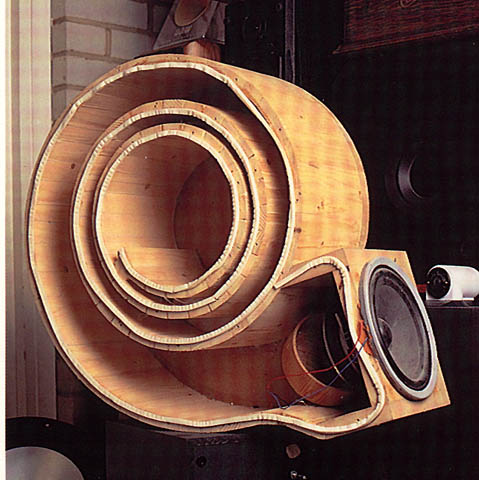
A nother example when you have a bass horn the horn has good loading down to say 50Hz. Under 50 Hz the impedance will rise. So in that case often also a BR-tube is placed in the closed volume of the frontloaded horn. So we have stil acoustic load under 50 Hz this wil work down to some where 45hz. So the you strech the output down to 45Hz with out BR loading it would fal of at 50Hz. So you win 5Hz.
Like in this picture a cone driver loaded at the front with a horn. The close volume is loaded with a BR-port.
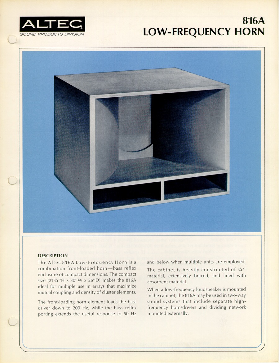
So you do not have to think in TL or BR or horn or open baffle. But in acoustic load for your cone-driver.
This you can see with a basreflex where the impedance is low at the tuning of the BR-tube. There at that frequency the tube causes good acoustic load.
The same with a good horn loading when the horn ensures good acoustic load there is no impedance peak. A peak means low acoustic load.
When you build a TL-tube look at what frequency the resonance peak occurs. The tune the TL at 1/4 of that wave length to have extra acoustic load at the resonance point.
Damping causes also a acoutic load only one you do not want. It is a dissipative acoustic load it only puts a brake on the cone of your driver. Damping is the wrong way to correct things, it damps also the dynamics you want to hear.
So you never shout use damping as solution, no make your system so that you will have acoustic load at the resonance point.
A nother example when you have a bass horn the horn has good loading down to say 50Hz. Under 50 Hz the impedance will rise. So in that case often also a BR-tube is placed in the closed volume of the frontloaded horn. So we have stil acoustic load under 50 Hz this wil work down to some where 45hz. So the you strech the output down to 45Hz with out BR loading it would fal of at 50Hz. So you win 5Hz.
Like in this picture a cone driver loaded at the front with a horn. The close volume is loaded with a BR-port.
So you do not have to think in TL or BR or horn or open baffle. But in acoustic load for your cone-driver.
Last edited:
A open baffle has low acoustic load and thus low efficiency.
A closed box has only acoustic load caused by the Sd area of the driver.
A BR is a closed box with a BR-port that ads extra acoustic load at the resonance frequency.
A horn is a cross-section area trans former the begin-area X movement = End area X movement. The driver in the horn thinks he has a Sd as big as the horn mouth. This give a huge acoustic load with the same weight of the cone. The end effect is high efficiency.
And with good loading at the resonance point there will be no impedance peak.
The point of a closed TL is to be able to ensure that any reflection from the far end has passed thru all the damping at least once, the idea being to totally kill any reflections & timesmear back thru the cone.
This was the advantage I was thinking of mostly, but I was under the impression it was accompanied by a flattened impedance response when correctly implemented.
I wonder now if I've built this 1/2 wave tube wrong. I've built it to the length of half the wavelength at resonance, should it be cut to 1/4 wavelength so that with the closed end the sound inside travels one 1/2 wavelength before retuning to the cone? That might explain any unexpected result if so. The graph is inverted as it's a graph of current, not impedance.
wcwarriner, I have vaguely heard of that sub and it is interesting. When I looked at the blue trace I thought to myself "if I added more tubes, I'd eventually end up with the impedance peaks spread to broadly and with such small magnitude that I'd create a system with an overall slightly higher impedance and flat", and I guess this is how the sub works. Only feasible on a limited bandwidth system like a sub though.
Helmuth, you are making it sound like there is indeed benefit to impedance flattening, in so much as it is representative of having placed a suitable acoustic load to the driver. This was my aim.
Thanks for all the input! Should I cut the tube in half, have I been doing this wrong?
In your case Dr em.
Make a pipe like the karlson example a open end with exponential opening.
Or when you want a closed end then the closed end shout be a exponential formed cilinder that closes the end of the TL.
Make a pipe like the karlson example a open end with exponential opening.
Or when you want a closed end then the closed end shout be a exponential formed cilinder that closes the end of the TL.
Last edited:
Or when you want a closed end then the closed end shout be a exponential formed cilinder that closes the end of the TL.
I suppose that looks a bit like this:
http://www.bowers-wilkins.co.uk/Discover/Discover/Technologies/Nautilus-Tapering-Tubes.html
?
I wonder now if I've built this 1/2 wave tube wrong. I've built it to the length of half the wavelength at resonance, should it be cut to 1/4 wavelength so that with the closed end the sound inside travels one 1/2 wavelength before retuning to the cone? That might explain any unexpected result if so. The graph is inverted as it's a graph of current, not impedance.
Helmuth, you are making it sound like there is indeed benefit to impedance flattening, in so much as it is representative of having placed a suitable acoustic load to the driver. This was my aim.
Thanks for all the input! Should I cut the tube in half, have I been doing this wrong?
No, 1/2 wavelength long at resonance was the right length for increasing the load and constraining cone motion. The question still remains what benefit you get.
With a standard TL (open ended) you get a few dB extra output from the backwave of the cone. You have to cut a fine line between bass output and ripple from line resonance, but you can do it. With a closed end pipe you loose that benefit. Having line length notch out your impedance curve may seem nice but what have you gained in the front radiating frequency response?
As you increase stuffing it just becomes a nonresonant sealed box, but since we can have woofer/box combos with any Q we want we don't need extraordinary measures to control resonance.
As I stated earlier, a flat impedance curve is not the goal. Flat radiated power is.
David S.
😛😛I suppose that looks a bit like this:
http://www.bowers-wilkins.co.uk/Discover/Discover/Technologies/Nautilus-Tapering-Tubes.html
?
I know the nautilus, i didn't think of it but they just done that with that shape.😎
It is a closed TL with exponential taper.
Although this looks more then a conical taper.
An externally hosted image should be here but it was not working when we last tested it.
Last edited:
- Status
- Not open for further replies.
- Home
- Loudspeakers
- Multi-Way
- Closed end TL experiments, impedance flattening