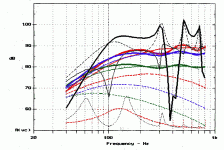
What I'm seeing is in the 1/2 wave TL without stuffing the original impedance peak has been flattened out, but replaced by 2 new peaks each of half the magnitude either side of the original. Why does this happen? When I had the MJK sheets I remember seeing something like this but I never really understood how to use them properly.
Your driver has a resonance at fs, you have tuned the length so that the pipe also has a fundamental resonance at fs (and higher harmonics). When you combine the two resonant systems, driver and pipe, the new system has two new resonances one below fs and one above fs and then the series of higher harmonics of the pipe (all shifted up slightly). You see this in many other speaker systems combining a driver loaded with a resonant enclosure like BR, TL, and some of the undersized BLH designs. Your plotted curves are exactly as expected and perfectly predictable.
Nice test and results.
Martin
Thanks MJK! I had a look at a BR system impedance on WinISD and it too exhibits 2 new resonances and a null at the tuning frequency as you describe, interesting.
Helmuth, it does look more conical actually yeah, unless the inside is exponential. I could slit my tube along its length and make it into a conical profile. Is the intention of this simply to 'swallow up' the back wave and make for clearer midrage reproduction?
I was looking at these closed end TLs mostly with this intention, that they can be used with a midrange driver, so is this the only advantage of one, that it provides a path along which stuffing can be placed and the rear wave absorbed efficiently? In this case perhaps it doesn't even need to be 1/2 wave?
Remember, if you change the profile to expanding or contracting and keep the same length you will shift the tuning frequency of the pipe up or down respectively. For an apples to apples comparison with your first experiment, you would need to change both the line's profile and length to maintain the same half wavelength tuning frequency.
Martin
Martin
I was looking at these closed end TLs mostly with this intention, that they can be used with a midrange driver, so is this the only advantage of one, that it provides a path along which stuffing can be placed and the rear wave absorbed efficiently? In this case perhaps it doesn't even need to be 1/2 wave?
It is definitely true that a well stuffed line doesn't need to be 1/2 wavelength. As you stuff it the effective length get longer (resonance drops) and with sufficient stuffing it isn't resonant at all so length becomes immaterial. I'd say any pipe that is 4 to 5 times its diameter in length will do exactly what you want.
Stay away from the Karlson stuff if you are looking for low resonance back absorbtion.
David
As you stuff it the effective length get longer (resonance drops) and with sufficient stuffing it isn't resonant at all so length becomes immaterial.
The only way the stuffed line can appear to get longer is if the effective speed of sound drops significantly. This has been shown to be a very minimal effect, the speed of sound passing through a fiber filled pipe does not change very much (< 10%). If you look at the original test data you can see that the peaks measured for the stuffed pipe appear at approximately the same frequencies as the empty pipe results.
Martin
The speed of sound may not vary drastically, but the resonance frequencies do go down. Augspurger shows the 1 wavelength dip (between the 3/4 resonance and 5/4 resonance) drop from 400 Hz to 300Hz with stuffing in his examples, a 33% wavelength increase. He gets the quarter wave resonance to drop from 100 Hz to 80 Hz.
David
The speed of sound may not vary drastically, but the resonance frequencies do go down. Augspurger shows the 1 wavelength dip (between the 3/4 resonance and 5/4 resonance) drop from 400 Hz to 300Hz with stuffing in his examples, a 33% wavelength increase. He gets the quarter wave resonance to drop from 100 Hz to 80 Hz.
So what is your explanation as to why this happens? Which plots are you looking at and comparing in his papers to make these observations?
Martin
So what is your explanation as to why this happens? Which plots are you looking at and comparing in his papers to make these observations?
Martin
6b on page 429 vs. 7b., 8a and 8b. on 430 and 431.
I don't need to explain it. You're the one who's skeptical. I'm just reporting what his study shows.
David
Having line length notch out your impedance curve may seem nice but what have you gained in the front radiating frequency response?
Complete removal of any energy from the rear of the speaker coming back thru the cone and adding a time-smeared signal to the front radiation.
dave
6b on page 429 vs. 7b., 8a and 8b. on 430 and 431.
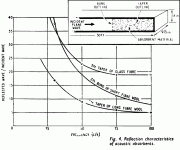
Attachments
6b on page 429 vs. 7b., 8a and 8b. on 430 and 431.
I don't need to explain it. You're the one who's skeptical. I'm just reporting what his study shows.
David,
I looked at the plots you referenced and it is pretty obvious what is going on in the TL. My results would match the paper's plots very closely for the same driver and geometry. The SPL peaks corresponding to output from the open end of the straight TL are at fairly constant frequencies as stuffing is added, there is a slight drop with additional stuffing. The SPL peaks are a little misleading, a phase plot would have been a better way to identify the TL systems resonant frequencies. The dips between the peaks are not indicators of resonances only how the quarter wavelength mode shapes above and below combine as frequency increases, the 100 Hz shift you noted is not really too significant.
Martin
😛😛
I know the nautilus, i didn't think of it but they just done that with that shape.😎
It is a closed TL with exponential taper.
Although this looks more then a conical taper.
An externally hosted image should be here but it was not working when we last tested it.
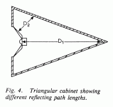
A.R. Bailey showed something like this in fig. 4 of his 1972 Wireless World article: The Transmisiion-line Loudspeaker Enclosure.
A.R. Bailey showed something like this in fig. 4 of his 1972 Wireless World article: The Transmisiion-line Loudspeaker Enclosure.
Here is Fig 4 from his 1975 WW : A Non-resonant Loudspeaker Enclosure.
I wasn't aware of any earlier articles on TLs... if you have something, i'd love a copy for my archives
dave
Attachments
Here is Fig 4 from his 1975 WW : A Non-resonant Loudspeaker Enclosure.
I wasn't aware of any earlier articles on TLs... if you have something, i'd love a copy for my archives
dave
PM me with an e-mail address and I'll send you a copy privately. I have a hard copy only and will scan it in. The file size will be too large to post here.
Last edited:
David,
I looked at the plots you referenced and it is pretty obvious what is going on in the TL. My results would match the paper's plots very closely for the same driver and geometry. The SPL peaks corresponding to output from the open end of the straight TL are at fairly constant frequencies as stuffing is added, there is a slight drop with additional stuffing. The SPL peaks are a little misleading, a phase plot would have been a better way to identify the TL systems resonant frequencies.
The dips between the peaks are not indicators of resonances only how the quarter wavelength mode shapes above and below combine as frequency increases, the 100 Hz shift you noted is not really too significant.
Martin
By the time he gets to moderate stuffing (7b) the dips and peaks are due to the time delay of the port output adding in and out of phase with the woofer output. This is evident from the lower curve of pipe output which becomes a broad and very smooth mound. In fact, hard to call the line "resonant" as the Q is very low. It is merely a bandpass of contribution. The phase curve (of the port output) won't show resonances in this case, only the smoothly lagging phase of a fixed time delay.
Still, the dips are the only noteworth feature and they do drop 100 Hz.
David
Last edited:
PM me with an e-mail address and I'll send you a copy privately. I have a hard copy only and will scan it in. The file size will be too large to post here.
Its OK, i figured out where i lead myself astray, by a decade, the non-resonant article is 1965, the one you refer to is the article with the triangulated TL. I have that. Fig 4 attached.
dave
Attachments
When quoting changes in frequencies having fairly large values, like 400 down to 300 Hz (a 25% change) or 100 down to 80 Hz (a 20% change), these changes due to stuffing seem much larger than they actually are. Applying them to a line whose unstuffed 1/4-wave resonant frequency is, say, 20-30 Hz, really doesn't end up with a very significant change, on the order of several Hz. The real problem is that the old TL myths about stuffing effects had people believing you could make a line half as long as needed, then be able to make it perform like it was twice as long as it was built simply by stuffing the c--p out of it, for instance. Martin can speak for himself and has already, but I think this is the point he's trying to get you to understand.
Paul
Paul
The speed of sound may not vary drastically, but the resonance frequencies do go down. Augspurger shows the 1 wavelength dip (between the 3/4 resonance and 5/4 resonance) drop from 400 Hz to 300Hz with stuffing in his examples, a 33% wavelength increase. He gets the quarter wave resonance to drop from 100 Hz to 80 Hz.
David
To me it seems that a TL with both ends closed, or a TL with one end open and a lot of stuffing, are both counterproductive, except for eliminating the time smear that Planet 10 refers to.
A TL that has one end open and judicious stuffing to reduce pipe resonances has the same advantage of a BR, that is, excursion of the driver is reduced in the frequency range bounding Fs while sound radiated from the open end of the TL keeps SPL constant.
Thanks for this great discussion,
Pete
A TL that has one end open and judicious stuffing to reduce pipe resonances has the same advantage of a BR, that is, excursion of the driver is reduced in the frequency range bounding Fs while sound radiated from the open end of the TL keeps SPL constant.
Thanks for this great discussion,
Pete
In my above post, I should have said judicious stuffing of UNWANTED pipe resonances, that is, the harmonic resonances. As I have read, the unwanted resonances in a TL with one end open are all odd harmonic.
In view of what I said in my above post #38, the fundamental resonance is helpful.
-Pete
In view of what I said in my above post #38, the fundamental resonance is helpful.
-Pete
When quoting changes in frequencies having fairly large values, like 400 down to 300 Hz (a 25% change) or 100 down to 80 Hz (a 20% change), these changes due to stuffing seem much larger than they actually are. Applying them to a line whose unstuffed 1/4-wave resonant frequency is, say, 20-30 Hz, really doesn't end up with a very significant change, on the order of several Hz. The real problem is that the old TL myths about stuffing effects had people believing you could make a line half as long as needed, then be able to make it perform like it was twice as long as it was built simply by stuffing the c--p out of it, for instance.
Paul
A drop from 400 to 300 is more than a third of an octave. I have to assume that the same relationships would hold true no matter what length (frequency) line you were working with.
I tend to agree that people have ascribed mythical qualities to TLs when, in truth they are a system of fairly marginal benefit. The open ended ("1/4 wave") system will give a bass level improvement: more output with slightly less cone motion. Still, to tame the upper modes you must compromise the bass gain. Augspurger was getting about 2 dB more bass in order to limit ripple to the same amount. The closed end TL makes no particular sense to me. I've built and measured enough boxes to know that it is fairly easy to absorb the back wave and kill all internal resonances in a woofer or midrange cavity. A modest amount of stuffing will negate any resonances rendering length largely irrelevant. The poster's own curves showed this with the 600 and 900 Hz resonances gone when stuffing was applied. Solutions like the B&W Nautilus are more marketing than science.
The 1/4 and 1/2 wave design notions are also outdated. "Tuning the box to the free air resonance of the driver" has long been discredited as a vented box design approach, but is still quoted for TL design. Augspurger showed, as Thiele and Small did with the vented box, that driver resonance wasn't a primary factor so defining length as 1/4 wave at resonance isn't valid. As with vented boxes, fs/Qt was a factor and a design that worked for a given unit would still be optimum over a wide range of driver compliances or resonant frequencies.
As soon as moderate stuffing is applied the length related resonance becomes heavily damped. The null in woofer cone motion disappears and vent output becomes low pass filtered rather than "tuned". All this makes a precise length irrelevant.
David S.
- Status
- Not open for further replies.
- Home
- Loudspeakers
- Multi-Way
- Closed end TL experiments, impedance flattening


