Hi All,
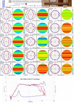
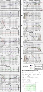
I've checked the suitability if using the Vifa-TC9FD18-08 Driver(3L Closed Box) with the posted EQ suggestion and found(IMO) that the EQ should be revised at the lower FR end...
b🙂
I've checked the suitability if using the Vifa-TC9FD18-08 Driver(3L Closed Box) with the posted EQ suggestion and found(IMO) that the EQ should be revised at the lower FR end...
b🙂
Attachments
-
 0-RR-vifa.JPG327.3 KB · Views: 501
 -
9-AA.txt4.9 KB · Views: 87
-
 8-Hi-Lo.JPG110.7 KB · Views: 626
 -
 7-TC9FD18-08_Polar-diff.JPG585.1 KB · Views: 488
 -
6-0dB-ref.txt6.8 KB · Views: 85
-
5-RR-Vifa-0-30degree-diff.txt6.9 KB · Views: 78
-
4-RR-Vifa-0-60degree-diff.txt7 KB · Views: 88
-
3-RR-Vifa-60-minPhase.txt15.2 KB · Views: 92
-
2-RR-Vifa-30-minPhase.txt12.6 KB · Views: 89
-
1-RR-Vifa-0-minPhase.txt9.8 KB · Views: 107
Last edited:
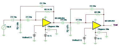
If I were building an IDS-25 Clone with the 3 inch Peerless/Vifa TC or TG drivers, this is the Active EQ circuit I would use. I haven't actually built this, but it should work fine. The graphs are the result of the SPICE models. I had to do each section separately due to limited page size in the free version of SPICE. If you can't get an exact R value, use one that's as close as you can. Same with caps. Verify operation on bench if possible before connecting into Hi-Fi system. After clicking on a graphic to make it big, you can click again on an icon in the lower left corner to make the image even bigger..
Bob,
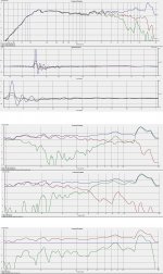
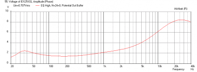
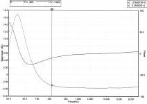
I am new at this, but giving it a shot by trying to simulate your circuit in Akabak. I am doing this to see the effect of using off-spec components in case I can't get certain values. Anyhow, I get the general shape of the EQ curves but the relative gain (amplitude) seems off. I am getting a lot lower gain in the low freq and higher in the high freq - not sure what I did wrong here. Anyhow, you do not show a combined curve, but my combined curve in the second plot looks not right. This is for a 0.707 volt rms input signal.
Let me know what you think, is this all wrong? I am also attaching the script below.
The first plot shows the individual response of each section, the second shows the combined plot. I am setting the potientiometer at the 1ohm:19ohm position.
Thanks,
X
Code:
|********************************************************
| Sim of Bob Richards IDS-25 EQ Circuit in Akabak
| XRK971, Sept 5, 2013
|
| Simulation: Inspect/Voltage (Level)

| Define operational amplifier
  Def_OpAmp  'Op1'
  vo=1e6  Rg=10ohm

System 'EQ High'

| #### SECTION 1 - High End Response EQ

  OpAmp  'Op1'  Def='Op1'  Node=2=3=4
  Capacitor  'C1'  Node=2=0  C=10nF
  Resistor  'R1'  Node=1=2  R=200ohm
  Resistor  'R2'  Node=2=0  R=50kohm
  Capacitor  'C2'  Node=5=0  C=3.9nF
  Resistor  'R3'  Node=3=5  R=50kohm
  Capacitor  'C3'  Node=6=0  C=1.5nF
  Resistor  'R4'  Node=3=6  R=6.8kohm
  Capacitor  'C4'  Node=7=0  C=330pF
  Resistor  'R5'  Node=3=7  R=1kohm
  Capacitor  'C5'  Node=3=4  C=82pF
  Resistor  'R7'  Node=3=4  R=40kohm
  Potential    'Out H-EQ'  Node=4=0

| #### SECTION 2 - Low End Response EQ


|System 'EQ Low'

  OpAmp  'Op2'  Def='Op1'  Node=9=10=11
  Capacitor  'C6'  Node=4=8  C=100nF  | (Node=4=8)
  Capacitor  'C7'  Node=8=9  C=100nF
  Resistor  'R8'  Node=9=0  R=50kohm
  Resistor  'R9'  Node=11=10  R=12kohm
  Resistor  'R10'  Node=10=0  R=9.6kohm
  Capacitor  'C8'  Node=11=12  C=100nF
  Capacitor  'C9'  Node=12=13  C=100nF
  Resistor  'R11'  Node=13=0  R=50kohm

  OpAmp  'Op3'  Def='Op1'  Node=13=14=15
  Resistor  'R12'  Node=15=14  R=12kohm
  Resistor  'R13'  Node=14=0  R=9.6kohm
  Resistor  'R16'  Node=12=15  R=50kohm
  Resistor  'R17'  Node=8=17  R=50kohm

  OpAmp  'Op4'  Def='Op1'  Node=17=18=19
  Resistor  'R14'  Node=15=18  R=12kohm
  Resistor  'R15'  Node=18=19  R=6.8kohm
  Capacitor  'C10'  Node=19=20  C=2.2uF
  Potential    'Out L-EQ'  Node=20=0

| #### SECTION 3 - Level Control Buffer and Line Driver


|System 'EQ Buffer'

  Resistor  'P1U'  Node=20=21  R=1kohm  | (node 20=21) Adjustment Pot upper
  Resistor  'P1L'  Node=21=0  R=19kohm   | Adjustment Pot lower set at 1:19 position

  OpAmp  'Op5'  Def='Op1'  Node=21=22=22
  Resistor  'R18'  Node=21=0  R=1Mohm
  Resistor  'R19'  Node=22=23  R=200ohm
  Capacitor  'C11'  Node=23=24  C=5uF
  Resistor  'R20'  Node=24=0  R=100kohm
  Potential    'Out Buffer'  Node=24=0  | Inspect this node for total ouput
Attachments

Bob,
I am new at this, but giving it a shot by trying to simulate your circuit in Akabak. I am doing this to see the effect of using off-spec components in case I can't get certain values. Anyhow, I get the general shape of the EQ curves but the relative gain (amplitude) seems off. I am getting a lot lower gain in the low freq and higher in the high freq - not sure what I did wrong here. Anyhow, you do not show a combined curve, but my combined curve in the second plot looks not right. This is for a 0.707 volt rms input signal.
Let me know what you think, is this all wrong? I am also attaching the script below.
The first plot shows the individual response of each section, the second shows the combined plot. I am setting the potientiometer at the 1ohm:19ohm position.
Thanks,
X
When you combined the two circuits in your modeling program, are you sure it combined them in series, rather than in parallel? The differential phase of the two circuits are mostly within 90 degrees of each other, often better than that, so I would think the combined response should be pretty close to what we want.
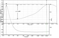
I couldn't figure out how to increase the gain of the low end EQ circuit without adding another opamp, since everything in that circuit is interactive and the math is over my head if I have to do any more than scaling of cap values to get the exact peak frequency I want, or playing around with those voltage dividers to adjust how high the peak is relative to the upper frequency level (which I don't know how to change without everything else changing too). So the low end EQ circuit ended up with a 3.5dB loss in the upper freqs, which I decided to make up for in the upper band EQ circuit which I have a much better understanding of.
Since the circuits are connected in series, dB's add. I designed the upper end EQ circuit to have a 6dB gain at about 250HZ, which would be the lowest gain point on the combined graph. I figured there would be a combined gain in the vicinity of (-3.5dB) + (+6dB) = +2.5dB, but since there's a phase issue when the two combine, the math of which is over my head, I knew that number would be off some. Probably not much since the differential phase is relatively small over most of the frequency range.
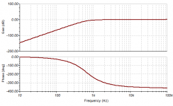
Sorry I forgot to plot phase on the upperend EQ graph, that I uploaded. I've since included it and will upload that if anyone wants to see it.
Thanks planet10 for suggesting png file types. I forgot... Here is a re-plot of both graphs showing phase as well. I would think they would combine petty well since the differential phase is relatively small over most of the frequency range., but I could be wrong.
I really needed to plot the combined circuits, but can't fit it all on the tiny page the free version of 5SPICE that I have allows. You have to pay money to get access to bigger page sizes. I have a new free version of SPICE from Linear Technology that's much more current, which may allow a bigger page size, but I'll have to remodel the whole circuit which may take another week. Other priorities are yanking at me.
I really needed to plot the combined circuits, but can't fit it all on the tiny page the free version of 5SPICE that I have allows. You have to pay money to get access to bigger page sizes. I have a new free version of SPICE from Linear Technology that's much more current, which may allow a bigger page size, but I'll have to remodel the whole circuit which may take another week. Other priorities are yanking at me.
Attachments
The gain we are trying to achieve is SPL (watts) at the speaker correct? Then the power is proportional to the voltage squared - would this help things? My simulation has the circuits in series. If you look at the script you will see that the last node of each section is the input node to the next section.
I'd wait to build this until I've had a chance to SPICE analyze the whole circuit, not just section by section, in case there's something unexpected about how they combine. Sorry about the delay on this.
Hi All,
I've checked the suitability if using the Vifa-TC9FD18-08 Driver(3L Closed Box) with the posted EQ suggestion and found(IMO) that the EQ should be revised at the lower FR end...
b🙂
Compared to the TG driver the TC would need a bit more boost to be equal in output. From what I remember doing my own sims the difference was roughly 5 Hz more extension with the TG driver. You could boost the TC a bit more but my plan was to just move the boost curve 5 HZ higher. (leaving you with a little less bottom extension)
Just a short notice on EQ of the IDS-25:
Easiest way to get correct in room response (and mayb also the best) is to use something like this :
Juice HiFi
I use this and is very satisfied with it.
Used a highly modified Behringer before converting to Audiolense.
Easiest way to get correct in room response (and mayb also the best) is to use something like this :
Juice HiFi
I use this and is very satisfied with it.
Used a highly modified Behringer before converting to Audiolense.
Do you still convert the audio files before playing them or do you use it in real time?
(I've been reading the user forums a while back)
(I've been reading the user forums a while back)
I do it real time using Foo2K and convolver.
To make converted files of all the musik on the server would take some time, and you have to do it again if you change anything..
But it can be done and actually the sound improves a little, probably because the CPU dosent have to work when the converted files are played (no convolver involved)
To make converted files of all the musik on the server would take some time, and you have to do it again if you change anything..
But it can be done and actually the sound improves a little, probably because the CPU dosent have to work when the converted files are played (no convolver involved)
I decided it was about time to get my own separate thread instead of riding in the back of old threads all over the place. It did bring new life to this one with interesting discussions and I do hope that vibe continues 😀.
My new thread: The making of: The Two Towers
Is this a good start? 😉
My new thread: The making of: The Two Towers
Wunderbar!
When you are done, it would probably be very useful to many of us here if you would take the time and describe the process of your build, as detailed as possible... This would be very very useful 😛
There are so many issues getting this right and obviously you did all the right choices, so we do have a lot to learn from you....
That is, if you can get away from listening to music when you're done with those speakers 😀
Is this a good start? 😉
Last edited:
Well, I spent many hours trying to get the new Linear Technology "LT SPICE" program to work with my IDS25 active EQ circuit, and I failed. The instructions are a joke (looks like pre-beta). When the results were way off with the whole circuit, I tried just the first opamp stage, which obviously creates a rise in ampltude as you go up in frequency. It showed the opposite. then I trying graphing only the voltage source, and even that was way off. Apparently you have to buy their book to find out how to use this program.
So, does anybody have any suggestion of where I can get a free SPICE program that actually works? My old one (5SPICE) works great, but unless you pay them money, the work space is too small for more than about 3 opamp circuits.
So, does anybody have any suggestion of where I can get a free SPICE program that actually works? My old one (5SPICE) works great, but unless you pay them money, the work space is too small for more than about 3 opamp circuits.
Here's my LTSPICE model in case anyone wants to troubleshoot it. I'm skeptical about the voltage source, but also I hear you have to actually somehow connect up power supplies to the opamps (not a default?). I may have done that wrong. I tried "+15V" vs "+V" like in one of their models, and neither worked.
Thanks for any help on this.
Thanks for any help on this.
Attachments
Bob,
Do you have a Linux or unix machine? If so, a fully capable spice is available free from UC Berkeley EECS department.
Spice
Otherwise you are stuck with paying for a full version on Windows or Mac. Alternatively, you can try AkAbak but that is limited to 55 nodes although an op amp uses only 3 nodes. But as you can see, I am not sure why my AkAbak model of your Spice circuit doesn't seem to produce the same amplitudes. Shape of the curve seems correct.
I'm running Win 7 Pro on my PC. I was going to buy 5spice (get it registered) so I could have bigger page sizes, when I couldn't get LTSPICE to work right after many hours, but it's too expensive ($219) since I'm just a hobbyist at this point (retired Eng. Tech.).Bob,
Do you have a Linux or unix machine? If so, a fully capable spice is available free from UC Berkeley EECS department.
Spice
Otherwise you are stuck with paying for a full version on Windows or Mac. Alternatively, you can try AkAbak but that is limited to 55 nodes although an op amp uses only 3 nodes. But as you can see, I am not sure why my AkAbak model of your Spice circuit doesn't seem to produce the same amplitudes. Shape of the curve seems correct.
I'm really surprised and disappointed that LTSPICE has such horrible documentation, and doesn't work right on such a simple circuit. I've been using other spice programs for decades no problem. When you analyze the output of their voltage source (set for 1 volt AC analysis), I would hope you'd get a flat FR up to 50kHZ..... but nooooooo... WTF. A whole day lost.
Is it this one (TINA) from TI you have tried?
SPICE-Based Analog Simulation Program - TINA-TI - TI Software Folder
SPICE-Based Analog Simulation Program - TINA-TI - TI Software Folder
Koldby,
Thanks for the tip on TINA! I just downloaded it and installed it. Works like a charm - fully loaded and free!
Here is the link to the manual in case anyone else is interested in the capabilities.
http://www.ti.com/lit/ug/sbou052a/sbou052a.pdf
I just ran a sample case (in examples) of a 4th order Bessel HP filter to make sure it works and it does. Below is the circuit and freq response output.
Thanks! I have another neat tool to work with that complements my Akabak modeling, and now have the ability to play in the electronics domain. 😀
(Bob Richards, this is what you have been looking for! - includes a lot of TI IC's in library for you to use like your favorite op amps and ADC or DAC's)
Attachments
You might also want to get TI's free Filter Pro software for designing LP/HP filters, phase/time shift/delay active filter circuits. Perfect complement to the TINA software.
Active Filter Design Application - FILTERPRO - TI Software Folder
Active Filter Design Application - FILTERPRO - TI Software Folder
- Status
- Not open for further replies.
- Home
- Loudspeakers
- Full Range
- Cloning IDS-25s