Many GB2 boards and mosfets delivered from Randall yesterday. Plus... Stickers!
I put together a List on Digikey for the Aleph 60 main board BOM. If the link doesn't work as a share, I've also attached my downloaded order spreadsheet.
https://www.digikey.com/en/mylists/list/HWBOAPPKUI
Also, I overbought on quantities because it's easier to have too many than not enough, so double-check your quantities.
Attachments
My bad: not included in the List/spreadsheet are:
R2,R2
R13
heatsink thermal pads
or any of the Qs Randall included in the group.
R2,R2
R13
heatsink thermal pads
or any of the Qs Randall included in the group.
Getting ready order up some build parts for the Aleph 30 and given the worsening parts situation going ahead and grabing what's needed for the 60 if I expand. Had a couple of general questions.
Plan is start off with dual mono PS in 4U deluxe chassis with Aleph 30, then will spread out to 2 chassis if Aleph 60 happens. With the dual PS is the Schurter power entry module in the deluxe rear parts kit GTG to run Live and Neutral x2 directly off back of switch? I understand the recommendation is also to put separate fuses on each Live line after the power entry module.
Is there enough room on the amplifier boards for Dale RN60 1/8W resistors? Standard Yaego/KOA are getting hard to hunt down but Mouser has all the sizes needed in the RN60 series but 8.7mm in length.
How about options for the 3W metal oxides? The recommended TE connectivity seems to a flame retardant metal film, not metal oxide. Are the Vishay wirewound 3W resistors an option? More expensive but at least in stock at Mouser for one stop shopping.
https://www.mouser.com/ProductDetail/Vishay-Dale/CW02B1R000JE12?qs=sGAEpiMZZMvNd0dY0KymzovlQjR29jmMNNIJTpLI78Q=
One last assembly question: any tricks to soldering Q1-3? With bigger Fets the legs and bent and attached to heatsink while soldering. Im obviously overlooking an easy way to stabilize Q1-3. And about Q1-2, I have IRF and Harris 9610s, as well as FQP3P20. My ignorant guess is the Harris 9610 has the potential to measure/perform better than its IRF counterpart. What about the FQP3P20? Different presentation like switching from stock IRF9610 to Toshiba 2SJ313?
ETA: What is the correct Neutrik XLR female jack to fit the 4U deluxe chassis cut out? Which of all the variations of the D series seems to fit/work the best?
https://www.neutrik.com/en/neutrik/products/xlr-connectors/xlr-chassis-connectors
Thanks
Last edited:
Hi CoGT3Is there enough room on the amplifier boards for Dale RN60 1/8W resistors? Standard Yaego/KOA are getting hard to hunt down but Mouser has all the sizes needed in the RN60 series but 8.7mm in length.
How about options for the 3W metal oxides? The recommended TE connectivity seems to a flame retardant metal film, not metal oxide. Are the Vishay wirewound 3W resistors an option? More expensive but at least in stock at Mouser for one stop shopping.
https://www.mouser.com/ProductDetail/Vishay-Dale/CW02B1R000JE12?qs=sGAEpiMZZMvNd0dY0KymzovlQjR29jmMNNIJTpLI78Q=
I wouldn't use 1/8W resistor instead I would check for some alternative.
The 1/4W resistor listed on the build guide are Yageo MFR series (MFR25FBF52-xxx) and some of these aren't available at the moment.
You can check for the MFR25FRF52 or MFR25FTF52. The only difference is the packaging. The former is bulk (FBF) while the other are taped (FRF) or box pack (FTF)
In post #25 I've shared a Mouser project. I've updated it with available parts for another forum user.
You can check it for reference
For the 3W 0.47 resistor I would check this
https://www.mouser.it/ProductDetail/KOA-Speer/MOSX3CT521RR47J?qs=m/CZjK2YaEJsJia8p8nbVQ==
Michele
Hi CoGT3,
The Rn60s look a bit too large. You might try filtering on size. CMF55/RN55 resistors should work well.
For the 3W 1 ohm resistor, you might consider this one:
https://www.mouser.ca/ProductDetail/YAGEO/FMP300FRF73-1R?qs=gt1LBUVyoHlzyt3CzTYnuA==
The Rn60s look a bit too large. You might try filtering on size. CMF55/RN55 resistors should work well.
For the 3W 1 ohm resistor, you might consider this one:
https://www.mouser.ca/ProductDetail/YAGEO/FMP300FRF73-1R?qs=gt1LBUVyoHlzyt3CzTYnuA==
The Dale RN are Mil spec and the usual understanding they are rated at 1/2 true rating so 1/8W are equivalent to standard 1/4W resistor however they tend to be bigger in size than the standard 1/4W.Hi CoGT3
I wouldn't use 1/8W resistor instead I would check for some alternative.
The 1/4W resistor listed on the build guide are Yageo MFR series (MFR25FBF52-xxx) and some of these aren't available at the moment.
You can check for the MFR25FRF52 or MFR25FTF52. The only difference is the packaging. The former is bulk (FBF) while the other are taped (FRF) or box pack (FTF)
In post #25 I've shared a Mouser project. I've updated it with available parts for another forum user.
You can check it for reference
For the 3W 0.47 resistor I would check this
https://www.mouser.it/ProductDetail/KOA-Speer/MOSX3CT521RR47J?qs=m/CZjK2YaEJsJia8p8nbVQ==
Michele
Good find on the KOA Metal Oxides, somehow they didn't show when I did a search in Mouser.
@CoGT3
IEC/Fuse/Switch then to individual channel fuse in the line/hot wire is the way to go. You want each donut individually fused.
I think others have covered the resistor questions.
Q1-3, drop them in and solder. There's no need to heatsink them. They just stand up on the board in the open.
The store chassis is set up for the neutrik XLR geometry. I recently use a NC3FDV-B. It is a PCB mount version, and I ordered in a hurry.
Next time I'd go for a solder cup version - DL series. For example: NC3FD-L-B-1

Thank you all, orders placed. Between Mouser and Digikey I was able to hunt everything down. Buy my prices have bumped since I ordered Aleph J/ACA mini parts 2-3 months ago.
Randy, thanks for confirming the PS hookup, I thought I had that straight. Ordered the DL series XLRs. Missed the little shoulder on the 9610s that I guess stop them from slipping through the boards.
Dennis, you are absolutely correct, I mean to search for RN55 in the first place. Late night is probably not the right time to make a build list but with 3 little kids in the house its my alone time. Between both sites I found all the needed resister in the RN55 series.
Know to repeat the process for M2x and a bunch of daughter boards, better to hoard the parts know.
Good day everyone. I realise today is 2 months from my having received the very kind gift of Randy's lottery amplifier boards.
I hope I haven't done you all an injustice but here I can sort of present a working amplifier.! No music yet unfortunately but that may happen very soon. This has taken a bit more time than I expected.....don't all our projects?!
So I built up the psu provided and using LT4320 for now just to keep some heat out i have 23v rails. Bias is 300mA at the moment.
PSU has 6x 15000uf and 2 x 22000. AC ripple measured is 100mv per rail which i assume is too much.
ICL at TH3 on the psu is pretty damn toasty! It is a 5.5A part. Maybe marginal. If 300ma is the whole psu drawing 7.6A?
Don't judge the wiring!
I need some clarification on the AC current gain procedure. Would this setup work? : Using a sound card, generate a 100hz signal which is then put through a pre-amp and then into the Aleph 30 input. Hook up the speaker out of Aleph into an 8 ohm dummy load, and adjust the pre-amp volume control on pre-amp until 16v ac is read on the speaker out leads into dummy load. Then measure voltage across resistors as explained.
I need some clarification on the AC current gain procedure. Would this setup work? : Using a sound card, generate a 100hz signal which is then put through a pre-amp and then into the Aleph 30 input. Hook up the speaker out of Aleph into an 8 ohm dummy load, and adjust the pre-amp volume control on pre-amp until 16v ac is read on the speaker out leads into dummy load. Then measure voltage across resistors as explained.
That will work. A few tips:
- 16V is nominal. I was doing 10V.
- Pick one of the source resistors to make your measurement. No need to do all. Just use the same one. The goal is to get the high & low measurements and then adjust to 50%. Any of the "lower" (output) source resistors will be fine for this.
- When doing your measuring with and without the jumper installed, adjust your preamp so the voltage on the dummy resistor is the same (10V, 16V, or whatever you choose). It will drift a little bit when the jumper is in or out.
I managed to get some rca and speaker connections rigged up yesterday and I actually had it playing music in my system. Very nice sounding too albeit a short audition. Seems very quiet despite maybe not having 'enough' capacitance in the psu, and definitely no ground loop issues. Although the 'work in progress' chassis is probably helping me there.
Sinks seem to reach and maintain 50c in the equipment rack. Plenty warm but isn't running away any more than that and I cam make some more room for it to breath hopefully. I might try a row of small fans along the bottom edge of the fins for peace of mind. Oh and it makes the meter spin, not a good time to have a 50% increase in energy bills.
Very please and glad to be part of the Pass fraternity finally. Shall update with more progress.
This is excellent! I'm so glad you got the music playing! I saw your last post when I was on a trip over the weekend and was waiting for this followup. It warms my heart (and your listening room) to see that you put together so quickly.I managed to get some rca and speaker connections rigged up yesterday and I actually had it playing music in my system. Very nice sounding too albeit a short audition. Seems very quiet despite maybe not having 'enough' capacitance in the psu, and definitely no ground loop issues. Although the 'work in progress' chassis is probably helping me there.
Sinks seem to reach and maintain 50c in the equipment rack. Plenty warm but isn't running away any more than that and I cam make some more room for it to breath hopefully. I might try a row of small fans along the bottom edge of the fins for peace of mind. Oh and it makes the meter spin, not a good time to have a 50% increase in energy bills.
Very please and glad to be part of the Pass fraternity finally. Shall update with more progress.
If it's quiet on your speakers, don't sweat the power supply capacitance. Most GreedyBoyz go really big (overkill) on power supply caps. Trust your ears!
It sounds like it runs plenty warm, but not dangerously hot. Room to breathe should help if it's in close quarters on a rack.
Cheers!!!
Thanks Randy I do appreciate that and again many thanks for the boards in the first place.
Even though I havent built the boards up, the reading I have done has really taught me a lot about biasing transistors and the like. All interesting stuff that has furthered my knowledge and enjoyment of this hobby.
I need to take the amp to my brothers at some point and try in place of his Vitus amp on his Avalon speakers.....think he may be surprised! Although I do need to tidy the wiring and sort thr chassis out.
Well done @jimk04, from your description everything is working out nicely. It gives great encouragement to finish up the chassis and get it playing. I'd say don't sweat the fans etc yet, get used to it and listen for a while and if it is crossing the late 50s in it's final home you can consider them.
Thanks Fran. I have definitely read it a lot more than once that 50c is OK. And the sinks / pads/ compound seem to be drawing it away from the devices quite nicely as they aren't too hot. Maybe come the middle of summer it might be too much but maybe it will have to be a 'winter amp'!
I've got mine up and running....sounding very nicely! Thanks to Randy and Nelson Pass!
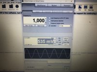
So I am dialing everything in, but my ac gain is too hot. I've got the following after sufficient warm-up:
DC offset 10mv
AC bias. 2.166
AC gain calculated with a 1000hz. 10vrms signal with jumper off into 8ohm load resistor: .1824 AC. With jumper on, 50% would be .0906, but I can only get .076 with the pot dialed max.
I did adjust so that it was 10vrms both with jumper on and off measurement. I also checked R21, and it is correct at 392.
I don't know enough to figure the next thing to do, so am hoping for some help.
Thanks,
Chris
Attachments

Chris,
For a sanity check, can you measure, with the jumper installed, the AC voltages across the 0.47R sources
resistors on the top half (R36-R39 where populated), and those (R40-R43 where populated) on the bottom half?
(For consistency, let's set the 10V RMS output at 8 ohm load)
Are the AC voltages pretty much the same across R36-R39? Across R40-R43? If the AC voltages are pretty consistent across each half, then just pick a representative on each half and see if you can get their AC voltages the same by adjusting P2.
If there are significant differences between the values within each half, how close can you get the sum of the top to the sum of the bottom by adjusting P2?
Last edited:
- Home
- Amplifiers
- Pass Labs
- Classic Aleph Amplifier for Modern UMS Chassis Builder's Thread