I've been looking for examples of class-g / class-h implemented using valves as the output devices, but cannot find any. This might be because of the search terms, or maybe nobody has...
Any links or references are welcome.
This is a purely academic exercise .... at the moment...
Any links or references are welcome.
This is a purely academic exercise .... at the moment...
^^^^
Tubelab (George) is working on something like that. Class H or G was never implemented back in "the day" since this requires lots of solid state electronics to pull it off.
Tubelab (George) is working on something like that. Class H or G was never implemented back in "the day" since this requires lots of solid state electronics to pull it off.
This scheme I think would qualify (as class G?) if the SS amp is running class AB, since the SS amp output backs up thru the tube output xfmr unless the tube conducts. So one could put a minimum B+ supply in the tube amp part, and the SS amp will supply the B+ variation needed for signals.
Depends on the gain settings of one amp versus the other as to how much "B+ overdrive" the SS amp will push back thru the OT. Ie, set the gain of the SS amp too high versus the tube feedback network ratio, and the tube amp will see its B+ vary with signal.
Of course, if you set the gain of both amps equal, then the tube amp will see constant B+, and will conduct with constant voltage across the tubes.
The tube amp, via its feedvack network, still defines the final output signal.
http://www.diyaudio.com/forums/showthread.php?postid=871030#post871030
Don
Tubelab (George) is working on something like that. Class H or G was never implemented back in "the day" since this requires lots of solid state electronics to pull it off.
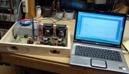
I built a SET amplifier that used a single 6336A tube per channel to make 38 watts at 5% distortion, 24 watts at 1%, and 10 watts at 0.33%. The key was a DSP controlled "modulated" switchmode power supply. The same amp will do over 20 watts with a 6AS7 tube. This amplifier was built for and submitted to a Microchip dsPIC design contest hosted by Circuit Cellar magazine. In a sea of microprocessor controlled gizmos, this vacuum tube amplifier won one of the prizes. The amp was finished just in time for the contest deadline (October) and hasn't been touched since due to seriously ill family members.
The magazine has stated that they are running a special issue highlighting all of the contest winners, and they have asked me to write a future article about the design, so it will come off of the shelf soon for some more experiments. I have also been experimenting with an "all tube" amplifier design incorporating some of the concepts developed during the design of the DSP amp. It will not have the efficiency improvements afforded by the DSP controlled SMPS, but should capture some of the distortion improvements. That design can be found here:
http://www.diyaudio.com/forums/showthread.php?s=&threadid=114021
The entire project submission including schematics and source code can be found on the Circuit Cellar web site here:
http://www.circuitcellar.com/microchip2007/winners/MT2209.html
Ever see a tube amp that you tweak with a laptop?
Attachments
George's idea is more akin to what I was imagining, with modulated rails and bias but I had no idea that a solution would be quite as complex. The word "impressed" would be a complete understatement!
I'm afraid my micro-controller program experience is almost zilch. Whenever I've sat down to learn, I've allowed myself to be distracted by something seemingly more interesting (often of the glowing variety)....
George, did you choose a cathode follower output stage for a particular reason?
I'm afraid my micro-controller program experience is almost zilch. Whenever I've sat down to learn, I've allowed myself to be distracted by something seemingly more interesting (often of the glowing variety)....
George, did you choose a cathode follower output stage for a particular reason?
John,
The two amplifier scheme I pointed out IS a modulated rail design. It's just not obvious unless you analyze it. The SS amplifier is providing a low voltage modulated rail output and that is fed backwards thru the output tranny to the tube amp to become HV modulated rails for each tube. The settings of the two feedback network gains is what determines how much B+ modulation will show up in the tube amp. Also the OT xfmr impedance ratio is important.
You probably are looking at it as a mostly SS amp with a little tube power added on. But that is the way ALL of the modulated rail designs work. The modulator is always effectively in series with the final amp stage and the modulator DOES put out most of the power itself. But the final amp stage (the tube amp here) is still what controls the final voltage output.
If you look at the Technics Class A+ designs, which use a Class AB amp to provide modulated rails for a low voltage Class A stage, you will see the series connection clearly.
The scheme I pointed out is actually a very elegant design since it avoids having to deal with HV modulators.
This is similar to the way the Berning Impedance converter generates HV for its tubes by feeding low voltage backwards thru the OT xfmr. Just not using a switching xfmr in this case. (So we have to supply the minimum DC B+ in the tube amp. since we can only push AC rail modulation back thru the conventional xfmr.)
The Berning imp. converter even could be made into a tracking rail design with PWM added to the switching imp. conv. The ripple free Cuk converter would be ideal there. (I have pointed this out in the past as a way to make a dynamically VARIABLE RATIO switching output xfmr. I better not see any patents filed on these! These are declared open to DIYers.)
Don
smoking-amp said:
The tube amp, via its feedvack network, still defines the final output signal.
http://www.diyaudio.com/forums/showthread.php?postid=871030#post871030
Don
How much of SS power will be dissipated on output tubes, and how this power will be reflected on working points of output tubes?
I mean, they don't have zero output impedance, right?
George, did you choose a cathode follower output stage for a particular reason?
The cathode follower was chosen for its high PSRR (power supply rejection ratio). The digital power supply solution that I have used here has 10 bit resolution. This means that the power supply will not be exactly what you expect. A cathode follower gives you about 30 db of isolation from the power supply imperfections. For this reasons most SS class H amps use source follower output configurations.
I had no idea that a solution would be quite as complex.
This particular implementation was meant to be a learning experience for me, and it was an entry into a dsPIC design contest. The dsPIC was required for this project, and it will allow for some serious experiments in the future.
The modulated supply concept can be implemented with mosfets or even vacuum tubes, but you will loose the efficiency enhancements afforded by the SMPS. I have working (sort of) examples of both designs that will be on my web site after I perfect them.
It is also possible to build the modulated supply without a microcontroller. You would need to modify the control circuitry of a conventional SMPS controller IC circuit. Look at some of the digital modulators being used by the high power ham radio operators for ideas. One example can be seen here:
http://www.classeradio.com/modulate.htm
Hi Anatoliy,
"How much of SS power will be dissipated on output tubes, and how this power will be reflected on working points of output tubes?"
As George just pointed out, the usual approach is to use followers, preferably pentode or hi-Z bipolar/Mosfets to get maximum PSRR. It is really, the Hi Z plate/collector/drain side that is giving the isolation from power supply. But follower mode also lowers the controlled side Z to help as well. Using a triode will work, but PSRR will suffer. Follower mode in the tube amp is not required with pentodes. With triodes, it would be necessary to get good PSRR.
So, as an example, first suppose the feedback network for the tube amp specifies Vout/Vin as 20. Using the same Vin for the SS amp, we set its feedback network to Vout/Vin as 20 also. Now the SS amp will be putting just the right voltage for the Tube amp to be happy. So the tube amp will be maintaining constant voltage across its pentodes (whatever the internal B+ supply is providing). The current thru the pentodes will be varying as the signal however, and the OT Z ratio determines how much current shows up there (and to be shown later, how much % power is delivered by the tube amp relative to the SS amp) (tube biasing will determine any additional DC component of current from the internal B+). The tube amp is not just loafing in this case (with a constant voltage across the tubes) however, it has to actively control the required current draw, so the grids are operating dynamically. Its a real amplifier, just not putting out extra power.
Now suppose the feedback network for the SS amp is set Vout/Vin = 22. The tube amp will now be unhappy with the signal output by the SS amp, so will allow the excess back primary voltage to additionally drop across the pentodes, ie, we now see effective B+ variation in the tube amp. (its magnitude depends on the OT Z ratio and how much excess voltage the SS amp generates.) Remember, the two amps are in series, so the tube amp can "eat" the output voltage of the other by dropping more V across the tubes if it sees fit to.
If we were to use triodes in the tube amp, their output Z will set a max voltage that can be "eaten" since the excess voltage appearing across the tube will eventually cause sufficient current flow to match the required load current draw. PSRR will suffer due to the plate resistance as well, so SS sound will bleed thru as well.
The OT Z ratio is set in a way to determine how much power will be delivered by the tube amp versus the SS amp. For a nominal 8 Ohm speaker load, the secondary winding on the tube amp xfmr will normally be considerably less than the usual 8 Ohm impedance. This is because of the rule that power out is V*V/Z. To provide10 Watts from the tube amp and 70 Watts from the SS amp, the peak voltage needs to increase from 47.3 Volts to 50.6 Volts. Notice that the increase of 3.3 Volts would not lead to 10 Watts if put into an 8 Ohm load. It has to be put into a lower Z in order to generate 10 Watts. The reason being that additional current is flowing here due to the SS amp.
I think I gave a formula for determining the tube amp secondary Z in the referenced thread, but its not too hard to work out the formula from the usual Ohms laws.
Don
Whups, forgot the third case.
If the SS amplifier feedback is set to Vout/Vin = less than 20, then the tube amp has to provide boost voltage to get the output up to snuff (Vout/Vin=20). So it now consumes some of its own internal DC B+ to generate the extra output like a normal amplifier would. So plates start swinging in phase with signal.
(in the earlier case, where the SS amp was putting out excess amplitude, the tube plates swing in opposite phase to the normal amplifier operation, effectively "eating" the extra power. Ie, plate voltages increasing when current increases.)
This 3rd case (SS putting out less than required), or the zero plate voltage variation case (SS putting out exactly that required), would correspond to the normal tracking rail amplifier cases.
But the excess output from the SS amp case demonstrates that the tube amp can correct the output to its liking no matter what distortion or variance the SS amp kicks out versus what the tube amp wants to see for output. (well, up till it runs out of internal B+)
Don
Don,
Apologies for doubting that yours was a true solution. I didn't look closely or for long enough.
I've been reading and re-reading your posts on this subject and agree that it is very elegant. However, I'm going to have to take some time to digest it.
Thanks for all your effort in posting and explaining.
No problem.
These combined amplifier schemes are a tuff cookie to digest at first. I didn't realize the tracking rail aspect of the scheme I referenced at first either. I just saw it as an easy way to put tube veneer onto a SS amp. Later I realized its real significance.
The original Technics Class A+ design eventually became too expensive to commercially sell and they simplified it till it no longer is the same thing. They call it Super Class A or something now.
Don
Don;
in George's case there was a cathode follower amp where a voltage between anode and cathode was held nearly constant due to SMPS that follows the input signal. As the result, a power dissipated on output tube was held constant and low; output resistance of a cathode follower is low due to very deep local feedback, and transients are good due to very short feedback path.
In your case 100W SS amp and 10W tube amp are connected in series with load; it means they work counter-phase to each other. The higher is output impedance of your tube amp, the more of SS power is dissipated on output tubes. It means, in order to make it workable your tube amp needs to have as low as possible output resistance. Your tube amp have to correct both own and SS amp's errors; it means it has to be very fast and feedback gain has to be proportionally good.
I played with such concepts a long time ago and found that A+C approach is the best in terms of quality and efficiency: A class and C class amps worked in parallel, and the solution was very simple (their voltage gains were selected correspondingly to their output resistances). THEIR OUTPUT CURRENTS SUMMED UP. Power needed from A class amp was low, and it was used to correct errors of class C amp instead of trying to "overcurrent" it like in your case.
Now, if to make A class and D class to work in parallel instead of working in series there will be a similar, but more efficient approach (D-class simulates C class, for example 2 opposite-paralleled diodes in series with D class output). I don't know if such a solution was already patented, though...
The output triode generates the least distortion when its plate to cathode voltage is held constant. The distortion is very low near .1% at the 1 watt level in my design. As the P-K voltage is allowed to vary (easy to adjust in a design like this) the distortion rises. It is mostly 2nd harmonic. This makes the distortion profile of the amp adjustable.
I am sure a similar effect will occur with Don's approach as the gain of the two amps is made unequal.
For now I intend to experiment further down the road that I have been following. There are all sorts of cool ideas that can be implemented in software on the hardware that I have developed. Some of them have already been translated back into "pure tube" designs, and some of them (the SMPS) never will. All will be added to our arsenal of available audio circuits.
I have a vision of an amplifier that you can hold in one hand that can put out 10 or more watts per channel with a pure tube class A SET audio path. Solid state power supplies and modulators will be needed to get there. I am not sure how to build it yet, but I am working on it.
Anatoliy,
Hmmm, where to start.
The load Z seen by the 10 Watt tube amp, at its tubes, is the same as it would see with just an 8 Ohm load by itself. This is due to the very low secondary Z of its transformer, as I mentioned. The power calculation rule for secondary Z, works out this way. It does not have to fight the mighty 100 Watt SS amp except for variations from the gain rules (ie distortion). But it only has to put these corrections into a load that looks like a normal 8 Ohm load due to the proper transformer ratio.
The tube amp actually has it easy. If the SS amp is putting out the correct gain (same gain rule as the tube amp) then the voltage on the tubes is constant at its internal B+, just like in George's design. No difference here. Switching artifacts or crossover distortions from the big amplifier are eliminated by the high PSRR of the small class A amplifier, thats why PSRR is so important.
The parallel amplifiers approach YOU mention is the one where one amplifier has to fight another bigger one. This approach has been tried many times, including with class D main amp. They have all been big disappointments due to the fact that the small amplifier must have extremely low output Z and extreme speed to knock out switching or crossover artifacts from the larger amplifier. Many papers have been published on this, they all were flops in practice. There are no successful commercial designs like this. You have the issues reversed.
There IS a way to fix the parallel amplifier case however, Yundt published a paper on it. (in the IEEE power conversion series, not the audio series, probably why the audio people never caught on.)
Don
tubelab.com said:
I am sure a similar effect will occur with Don's approach as the gain of the two amps is made unequal.
Don's approach is yours generalized. It means, gain of SS amp has to be tuned such a way so output toobs always see the same A-K voltage.
It means high gain SS part may be feed from anodes.
Now, if a SS part is switching-mode one we may use a small HF output transformers (one per tube) and fast rectifying diodes (one rectifier per tube) to power tubes, right? We don't need anymore a big expensive audio output transformer... but...
...but it seems to me I saw already such a patent.
Don;
in both cases amps fight against each other; but in my case they supply output currents in phase. Both of them have output resistances; both of them have gains; and the better voltage gains multiplied by output resistances match the better is linearity as the result of approximation. Since crossover regions are shifted on higher power levels their impact is inaudible compared to traditional A+B approach. Class C (or C simulated by D) decreases current demand from class A amp while a voltage demand is increased as the result of loss on an output resistance.
In your case SS amp fighting against the tube one increases it's current demand, but indeed when properly tuned it may hold constant current on anodes decreasing a voltage demand that is good to linearize triodes removing dependence of anode resistance on voltage (except errors of such a compensation of course that has to be compensated by a common feedback).
i.e. your approach is good as a means of linearization of triodes while mine is good as a means of building teethcrushers of very good sonical quality.
Once more:
your approach: increases current demand, decreases voltage demand, linearizes triodes.
my approach: increases voltage demand, decreases current demand, allows to build teethcrushers with high quality of sound and relatively low power dissipation.
smoking-amp said:
The parallel amplifiers approach YOU mention is the one where one amplifier has to fight another bigger one. This approach has been tried many times, including with class D main amp. They have all been big disappointments due to the fact that the small amplifier must have extremely low output Z and extreme speed to knock out switching or crossover artifacts from the larger amplifier. Many papers have been published on this, they all were flops in practice. There are no successful commercial designs like this. You have the issues reversed.
in both cases amps fight against each other; but in my case they supply output currents in phase. Both of them have output resistances; both of them have gains; and the better voltage gains multiplied by output resistances match the better is linearity as the result of approximation. Since crossover regions are shifted on higher power levels their impact is inaudible compared to traditional A+B approach. Class C (or C simulated by D) decreases current demand from class A amp while a voltage demand is increased as the result of loss on an output resistance.
In your case SS amp fighting against the tube one increases it's current demand, but indeed when properly tuned it may hold constant current on anodes decreasing a voltage demand that is good to linearize triodes removing dependence of anode resistance on voltage (except errors of such a compensation of course that has to be compensated by a common feedback).
i.e. your approach is good as a means of linearization of triodes while mine is good as a means of building teethcrushers of very good sonical quality.
Once more:
your approach: increases current demand, decreases voltage demand, linearizes triodes.
my approach: increases voltage demand, decreases current demand, allows to build teethcrushers with high quality of sound and relatively low power dissipation.
This is an edit to my previous post that got in too late:
Maybe the confusing factor here is due to the fact that low output Z is required to drive the speaker, and normally a tube amplifier feedback would be arranged to make a low output Z across the xfmr secondary. That is not the case here. The output Z of the secondary is not being forced low here, it actually is being forced high. What is being forced to low Z is the sum point, or total output, to the speaker. The tube feedback is NOT differentially monitoring just the tube amplifier's output.
Now on to Anatoliy's next post:
"It means, gain of SS amp has to be tuned such a way so output toobs always see the same A-K voltage."
This is easy to do, just use the same gain ratio for feedback networks in both amplifiers. Then the SS amp provides correct gain and the tube voltages stay constant except of distortion or crossover errors in the SS amp. The tube amp just acts as a tiny distortion "corrector" (or un-corrector depending on one's viewpoint)
"Now, if a SS part is switching-mode one we may use a small HF output transformers (one per tube) and fast rectifying diodes (one rectifier per tube) to power tubes, right? We don't need anymore a big expensive audio output transformer... but...
...but it seems to me I saw already such a patent."
Yes, D. Berning's impedance converter patent. We would have to modify it to provide PWM variation of the tube rail voltages. The Cuk (pronounced Shuk) converter is one which can do PWM without ripple. We would use this instead.
Don
smoking-amp said:
Now on to Anatoliy's next post:
"It means, gain of SS amp has to be tuned such a way so output toobs always see the same A-K voltage."
This is easy to do, just use the same gain ratio for feedback networks in both amplifiers. Then the SS amp provides correct gain and the tube voltages stay constant except of distortion or crossover errors in the SS amp. The tube amp just acts as a tiny distortion "corrector" (or un-corrector depending on one's viewpoint)
No, it can't be tiny. It will dissipate (I^2)*Rp. For best power transfer RL should be equal to Rp, i.e. it will dissipate power equal to output one, otherwise toobs will see variable anode voltages.
,,,now, the question is: do we actually need to eliminate the 2'nd order distortions keeping anode voltages constant if anyway the class A amp is push-pull?
"in both cases amps fight against each other; but in my case they supply output currents in phase. Both of them have output resistances; both of them have gains; and the better voltage gains multiplied by output resistances match the better is linearity as the result of approximation."
See my comment in my above post about the tube amp differential or secondary output Z actually being high from the feedback. (not to be confused with the low Z OT secondary ratio, this is for power handling matchup)
This is just like a Mosfet follower with modulated supply to picture it more simply. The SS amp provides the Drain voltage. The drain (think tube amp bottom secondary terminal) impedance is high, so PSRR is good. The source follower terminal then is however low Z due to the internal follower feedback.
This is exactly what the tube amp feedback does, keeps the output terminal to the speaker at low Z with respect to ground by means of feedback. I don't see any fighting between amplifiers here. But true, the better the SS amp adheres to the gain rule, the less the tube amp has to do.
Yes, keeping the voltage across the tube constant minimizes tube plate resistance effects or SS sound bleedthru, but a pentode is still preferred, so we don't have to use cathode follower mode.
"your approach: increases current demand, decreases voltage demand"
Well, yes it decreases voltage demand on the tube by keeping it constant. But current variation on the tube remains the same as if it were a 10 Watt amplifier driving an 8 Ohm load due to the low secondary Z ratio of the OT.
Don
- Status
- Not open for further replies.
- Home
- Amplifiers
- Tubes / Valves
- Class-g / class-h